

Discover how to manage both the direction and velocity of a DC motor utilizing an ESP8266 NodeMCU board alongside the L298N Motor Driver. Initially, we’ll elucidate the functionality of the L298N motor driver. Subsequently, we’ll guide you through the process of regulating the speed and direction of a DC motor employing the L298N motor driver with the ESP8266 programmed through Arduino IDE.
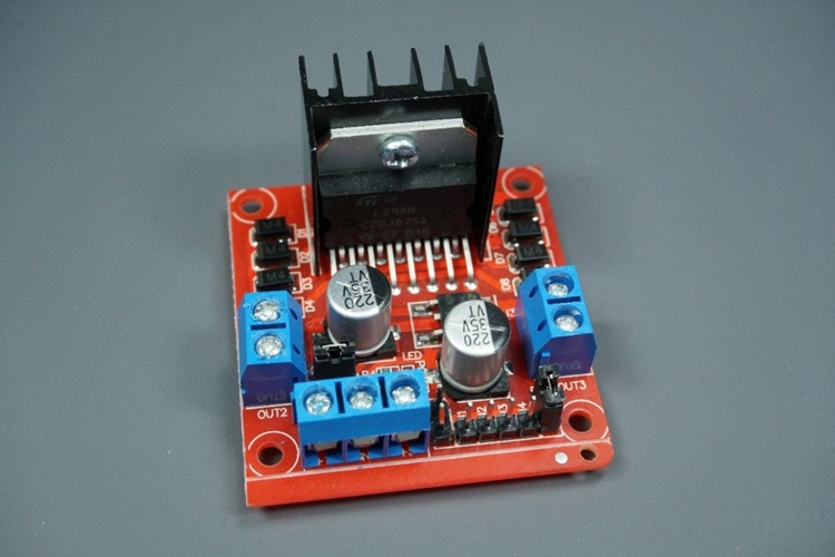
Introducing the L298N Motor Driver
There are numerous methods to regulate a DC motor. The approach we’re adopting here is suitable for most hobbyist motors, requiring either 6V or 12V to function.
We’ll utilize the L298N motor driver, capable of handling up to 3A at 35V. Moreover, it facilitates the simultaneous operation of two DC motors, making it ideal for constructing robots. If you’re employing a different motor driver, fret not, as most modules function similarly with identical input and output pins.
The pinout of the L298N motor driver is depicted below:
L298N Motor Driver Pinout
Let’s delve into the pinout of the L298N motor driver and comprehend its operation.
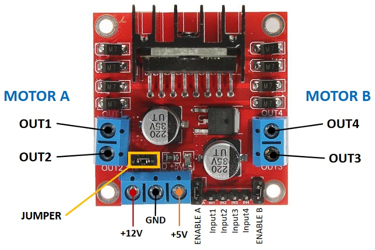
For each motor, the motor driver possesses a two-terminal block on both sides: OUT1 and OUT2 on the left, and OUT3 and OUT4 on the right.
- OUT1: DC motor A’s positive terminal
- OUT2: DC motor A’s negative terminal
- OUT3: DC motor B’s positive terminal
- OUT4: DC motor B’s negative terminal
At the bottom, a three-terminal block is present with +12V, GND, and +5V. The +12V terminal block is utilized to power the motors, while the +5V terminal powers the L298N chip. However, if the jumper is connected, the chip draws power from the motor’s power supply, obviating the need to supply 5V through the +5V terminal.
Crucially, notwithstanding the name +12V, any voltage between 5V and 35V (preferably within 6V to 12V) can be supplied.
Note: If supplying above 12V, remove the jumper and provide 5V to the +5V terminal.
In this tutorial, we’re employing 4 AA 1.5V batteries yielding roughly 6V combined output, though any suitable power supply may be used. For instance, a bench power supply is suitable for testing this tutorial.
To recap:
- +12V: Connect the motor’s power supply here.
- GND: Power supply ground.
- +5V: Supply 5V if the jumper is removed; otherwise, it acts as a 5V output.
- Jumper: With the jumper in place, the chip is powered by the motor power supply. Remove the jumper if supplying more than 12V; provide 5V to the +5V terminal.
At the bottom right, four input pins and two enable terminals are present. The input pins regulate the direction of your DC motors, while the enable pins manage their speed.
- IN1: Input 1 for Motor A
- IN2: Input 2 for Motor A
- IN3: Input 1 for Motor B
- IN4: Input 2 for Motor B
- EN1: Enable pin for Motor A
- EN2: Enable pin for Motor B
By default, jumper caps are attached to the enable pins. Remove these caps to control your motors’ speed; otherwise, they’ll either halt or operate at maximum speed.
Control DC motors with the L298N Motor Driver
Now that you have a grasp of how the motor driver operates, let’s delve into how to utilize it for controlling a DC motor.
Enable Pins
The enable pins function as an ON and OFF switch for the motors. For instance:
- Sending a HIGH signal to enable pin 1 activates motor A and sets it to maximum speed.
- Sending a LOW signal to enable pin 1 deactivates motor A.
- Sending a PWM signal allows for motor speed control. The motor’s speed is directly proportional to the duty cycle. However, it’s important to note that for low duty cycles, the motors may not spin and instead produce a continuous buzzing sound.
| SIGNAL ON THE ENABLE PIN | MOTOR STATE |
|---|---|
| HIGH | Motor enabled |
| LOW | Motor not enabled |
| PWM | Motor enabled: speed proportional to the duty cycle |
Input pins
The input pins determine the direction of motor rotation. Input 1 and input 2 dictate the behavior of motor A, while input 3 and input 4 govern motor B.
When input 1 receives a LOW signal and input 2 a HIGH signal, the motor rotates forward.
Conversely, applying a HIGH signal to input 1 and a LOW signal to input 2 results in the motor rotating backward. The same principle applies to controlling motor B, utilizing input 3 and input 4.
For instance, for motor A, the logic is as follows:
| Direction | Input 1 | Input 2 | Enable 1 |
| Forward | 0 | 1 | 1 |
| Backwards | 1 | 0 | 1 |
| Stop | 0 | 0 | 0 |
Controlling 2 DC Motors – Perfect for Robot Construction
When constructing a robot car employing two DC motors, it’s crucial that these motors rotate in specific directions to facilitate the robot’s movements: left, right, forward, or backward.
For instance, to propel the robot forward, both motors must rotate in the forward direction. Similarly, to maneuver it backward, both motors should rotate in reverse.
To initiate a turn in one direction, you’ll need to increase the speed of the motor opposite to the intended turn. For instance, to execute a right turn, activate the motor on the left while deactivating the motor on the right. The table below illustrates the various combinations of input pin states corresponding to the robot’s directional movements.
| DIRECTION | INPUT 1 | INPUT 2 | INPUT 3 | INPUT 4 |
|---|---|---|---|---|
| Forward | 0 | 1 | 0 | 1 |
| Backward | 1 | 0 | 1 | 0 |
| Right | 0 | 1 | 0 | 0 |
| Left | 0 | 0 | 0 | 1 |
| Stop | 0 | 0 | 0 | 0 |
Controlling a DC Motor with ESP8266 NodeMCU – Managing Speed and Direction
Now that you’ve grasped how the L298N motor driver operates and how to regulate a DC motor, let’s construct a straightforward example sketch to oversee the speed and direction of a single DC motor using the ESP8266.
Wiring a DC Motor to the ESP8266 (L298N Motor Driver)
The motor under our control is linked to the motor A output pins, necessitating the connection of the ENABLEA, INPUT1, and INPUT2 pins of the motor driver to the ESP8266. Refer to the schematic diagram below to wire the DC motor and the L298N motor driver to the ESP8266 NodeMCU board.
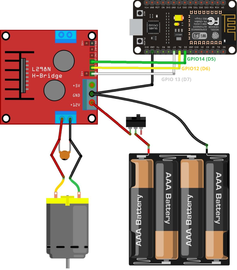
We’re utilizing the GPIOs detailed in the subsequent table to establish connections with the motor driver. However, you can opt for any other suitable GPIOs provided you modify the code accordingly.
| LN298N Motor Driver | Input 1 | Input 2 | Enable | GND |
| ESP8266 | GPIO 12 (D6) | GPIO 14 (D5) | GPIO 13 (D7) | GND |
Powering the L298N Motor Driver
Due to the substantial surge in current required to set the DC motor in motion, it’s imperative to power the motors via an external power source. For instance, we’re employing 4AA batteries, yet any other suitable power supply suffices. In this setup, a power supply ranging from 6V to 12V is viable.

On the schematic diagram, the inclusion of a switch between the battery holder and the motor driver is discretionary but practical for power control. This obviates the need for constant wire connections and disconnections to conserve power. Additionally, battery holders equipped with a button are available.
We advise soldering a 0.1uF ceramic capacitor to the positive and negative terminals of the DC motor, as delineated in the diagram, to aid in mitigating voltage spikes. (Note: the motors are operational even without the capacitor.)
Code: ESP8266 with a DC Motor – Speed and Direction Control
The following code orchestrates the speed and direction of the DC motor. While this code may not find direct application in practical scenarios, it serves as an excellent illustration for comprehending how to manage the speed and direction of a DC motor using the ESP8266.
// Motor A
int motor1Pin1 = 12;
int motor1Pin2 = 14;
int enable1Pin = 13;

// Setting minimum duty cycle
int dutyCycle = 60;

void setup() {
  // sets the pins as outputs:
  pinMode(motor1Pin1, OUTPUT);
  pinMode(motor1Pin2, OUTPUT);
  pinMode(enable1Pin, OUTPUT);

  Serial.begin(115200);

  // testing
  Serial.print("Testing DC Motor...");
}

void loop() {

  //Apply power to spin at maximum speed
  digitalWrite(enable1Pin, HIGH);

  // Move the DC motor forward at maximum speed
  Serial.println("Moving Forward");
  digitalWrite(motor1Pin1, LOW);
  digitalWrite(motor1Pin2, HIGH);
  delay(2000);

  // Stop the DC motor
  Serial.println("Motor stopped");
  digitalWrite(motor1Pin1, LOW);
  digitalWrite(motor1Pin2, LOW);
  delay(1000);

  // Move DC motor backwards at maximum speed
  Serial.println("Moving Backwards");
  digitalWrite(motor1Pin1, HIGH);
  digitalWrite(motor1Pin2, LOW);
  delay(2000);

  // Stop the DC motor
  Serial.println("Motor stopped");
  digitalWrite(motor1Pin1, LOW);
  digitalWrite(motor1Pin2, LOW);
  delay(1000);

  // Move DC motor forward with increasing speed
  digitalWrite(motor1Pin1, HIGH);
  digitalWrite(motor1Pin2, LOW);
  while (dutyCycle <= 255){
    analogWrite(enable1Pin, dutyCycle);
    Serial.print("Forward with duty cycle: ");
    Serial.println(dutyCycle);
    dutyCycle = dutyCycle + 5;
    delay(500);
  }
  dutyCycle = 60;
}
Declaring motor pins
Initially, you define the GPIOs linked to the motor driver. Here, Input 1 for motor A is assigned to GPIO 12, Input 2 to GPIO 14, and the Enable pin to GPIO 13.
int motor1Pin1 = 12;
int motor1Pin2 = 14;
int enable1Pin = 13;
Setting minimum duty cycle
To regulate the motor’s speed, the duty cycle of the PWM signal is adjusted. The minimum duty cycle is set to 60 to avoid peculiar buzzing sounds when the duty cycle is too low.
int dutyCycle = 60;
setup()
In the setup(), initiate by configuring the motor pins as outputs and initializing the Serial Monitor for debugging purposes:
pinMode(motor1Pin1, OUTPUT);
pinMode(motor1Pin2, OUTPUT);
pinMode(enable1Pin, OUTPUT);
Serial.begin(115200);
Moving the DC motor forward
Within the loop(), the motor is set in motion. Each part of the code is meticulously commented on its functionality. To empower the motors and propel them at maximum speed, the enable pin is set to HIGH.
digitalWrite(enable1Pin, HIGH);
To advance the motor forward, input 1 is set to LOW while input 2 is set to HIGH. In this demonstration, the motor moves forward for a duration of 2 seconds (2000 milliseconds).
// Move the DC motor forward at maximum speed
Serial.println("Moving Forward");
digitalWrite(motor1Pin1, LOW);
digitalWrite(motor1Pin2, HIGH);
delay(2000);
Moving the DC motor backwards
To reverse the DC motor’s rotation, power is supplied to the motor input pins in the reverse configuration: HIGH to input 1 and LOW to input 2.
// Move DC motor backwards at maximum speed
Serial.println("Moving Backwards");
digitalWrite(motor1Pin1, HIGH);
digitalWrite(motor1Pin2, LOW);
delay(2000);
Stop the DC motor
To halt the DC motor’s operation, either set the enable pin to LOW or set both input 1 and input 2 pins to LOW. In this instance, both input pins are set to LOW.
// Stop the DC motor
Serial.println("Motor stopped");
digitalWrite(motor1Pin1, LOW);
digitalWrite(motor1Pin2, LOW);
delay(1000);
Controlling the DC motor speed
Speed control of the DC motor is achieved by modulating the PWM signal duty cycle. This is accomplished using the analogWrite() function, specifying the GPIO pin and the duty cycle as arguments.
analogWrite(enable1Pin, dutyCycle);
In the provided example, a while loop incrementally increases the duty cycle by 5 in each iteration.
// Move DC motor forward with increasing speed
digitalWrite(motor1Pin1, HIGH);
digitalWrite(motor1Pin2, LOW);

while (dutyCycle <= 255){
  analogWrite(enable1Pin, dutyCycle);
  Serial.print("Forward with duty cycle: ");
  Serial.println(dutyCycle);
  dutyCycle = dutyCycle + 5;
  delay(500);
}
Once the while condition is no longer met, the duty cycle is reset to 60.
dutyCycle = 60;
Demonstration
Once the code has been uploaded to the ESP8266, power should be applied to the motor driver.

The motor will initiate rotation, exhibiting varying directions and speeds.
Wrapping Up
In this tutorial, we’ve elucidated the process of controlling the direction and speed of a DC motor utilizing an ESP8266 and the L298N motor driver. To summarize:
- To dictate the direction of the DC motor’s rotation, manipulate the input 1 and input 2 pins. Apply a LOW signal to input 1 and a HIGH signal to input 2 to induce forward rotation.
- Reverse the application of power to achieve backward rotation.
- To regulate the speed of the DC motor, administer a PWM signal to the enable pin. The motor’s speed is commensurate with the duty cycle.
We trust you’ve found this tutorial beneficial.
- ESP8266 NodeMCU: MAX6675 Amplifier for Precise Thermocouple Readings
- DIY Water Quality Testing: ESP8266 NodeMCU and TDS Sensor
- Step-by-Step Guide: ESP8266 NodeMCU + Stepper Motor (28BYJ-48) Setup
- DIY Digital Scale: ESP8266 NodeMCU & Load Cell + HX711 Amplifier Setup


