

One of the best things about ESP8266 is that its firmware can be updated wirelessly. This kind of programming is called “Over-The-Air” (OTA).
What is OTA programming in ESP8266?
OTA programming in ESP8266 stands for “Over-The-Air” programming. It is a feature that allows you to update the firmware of the ESP8266 microcontroller wirelessly, without the need for physical connections such as USB cables.
With OTA programming, you can upload new code or sketches to the ESP8266 module over a Wi-Fi network, making it a convenient and efficient way to update devices remotely. This feature is especially beneficial when the ESP8266 is deployed in locations that are difficult to access physically, as it eliminates the need to physically connect to each device for updates.
Using OTA programming, you can update multiple ESP8266 devices on the same Wi-Fi network from a central location, making it a convenient method for managing and maintaining a fleet of devices. It saves time and effort in updating and maintaining multiple devices.
The OTA functionality is achieved by incorporating OTA code within the sketches uploaded to the ESP8266. Once OTA capability is included in the initial sketch, subsequent updates can be sent wirelessly to the ESP8266 without requiring any direct physical intervention.
Parts Required
| Component Name | Buy Now |
| ESP8266 NodeMCU CP2102 | Amazon |
3 Simple Steps for Using OTA with the ESP8266
Using OTA with the ESP8266 is a simple process that involves three steps:
- Installing Python 3.11.x series: Start by installing the Python 3.11.x series on your computer.
- Uploading Basic OTA Firmware Serially: Upload the sketch containing the OTA firmware serially to the ESP8266. This initial step is necessary to enable subsequent updates to be performed wirelessly.
- Uploading New Sketch Over-The-Air: Once the basic OTA firmware is uploaded, you can now easily upload new sketches to the ESP8266 directly from the Arduino IDE over-the-air. This means you can update the ESP8266’s firmware without the need for physical connections, making the process efficient and convenient.
Step 1: Install Python 3.11.x series
To use OTA functionality with the ESP8266, the first step is to install the Python 3.11.x series on your computer. If you don’t have Python 3.11.x installed already, you can download it from the official Python website.
Here are the steps to install Python 3.11.x:
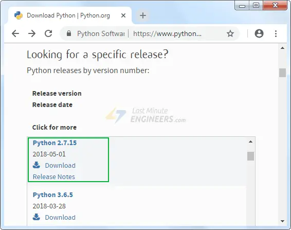
Download Python 3.11.x: Go to the official Python website (python.org) and download the installer for Python 3.11.x that matches your operating system (e.g., Windows, macOS, or Linux).
Launch the installer: Run the downloaded installer and launch the Python 3.11.x installation wizard.
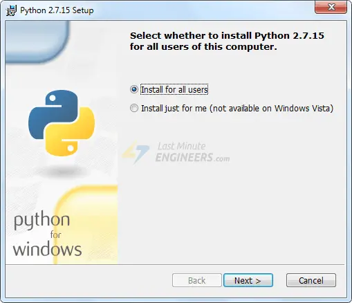
Proceed with the installation: Follow the on-screen instructions in the installation wizard to complete the installation process. You can choose the installation directory and customize the installation options as needed.
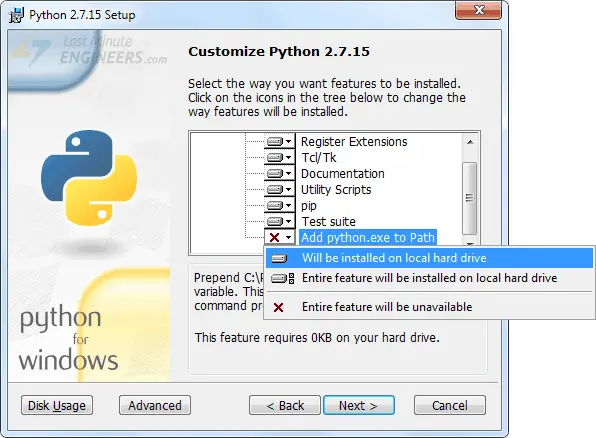
Enable “Add python.exe to Path”: During the installation, ensure that you enable the option to “Add python.exe to Path.” This option allows you to use Python from the command line without specifying the full path to the executable.
Complete the installation: Finish the installation process by clicking “Install” or “Finish,” depending on the prompts in the installation wizard.
Once Python 3.11.x is installed on your computer, you can proceed with the next steps to use OTA functionality with the ESP8266.
Step 2: Uploading Basic OTA Firmware Serially
To enable Over-The-Air (OTA) updates for the ESP8266, you need to first load the OTA firmware onto the ESP8266 using the serial interface. This is necessary as the ESP8266’s factory image does not have OTA upgrade capability. The OTA firmware update enables subsequent updates to be performed wirelessly.
Follow these steps to upload the Basic OTA firmware serially:
Download the ESP8266 Add-on: If you haven’t already, make sure you have installed the ESP8266 board package in your Arduino IDE. To do this, go to “File” > “Preferences” and in the “Additional Boards Manager URLs” field, add the following URL: http://arduino.esp8266.com/stable/package_esp8266com_index.json. Then, go to “Tools” > “Board” > “Boards Manager” search for “ESP8266,” and click “Install” to add the board package.
Choose the Correct Board: After installing the ESP8266 board package, go to “Tools” > “Board,” and select the appropriate ESP8266 board that matches your module, such as NodeMCU or WeMos D1 Mini.
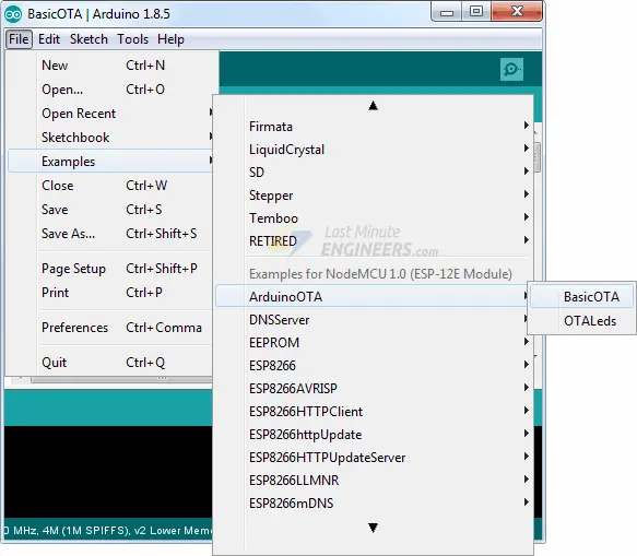
Open the BasicOTA Example: Go to “File” > “Examples” > “ArduinoOTA” > “BasicOTA” to open the BasicOTA example sketch.
Modify Network Credentials: Before uploading the sketch, you need to modify the following two variables in the sketch with your Wi-Fi network credentials. Replace the placeholders (“……….”) with your actual SSID (Wi-Fi name) and password.
const char* ssid = "..........";
const char* password = "..........";
Connect ESP8266 via USB: Connect your ESP8266 module to your computer using a USB cable.
Select the Correct Port: In the Arduino IDE, go to “Tools” > “Port,” and select the appropriate port that corresponds to your connected ESP8266 module.
Upload the Sketch: Click on the “Upload” button (the right-pointing arrow) in the Arduino IDE to upload the Basic OTA firmware to the ESP8266.
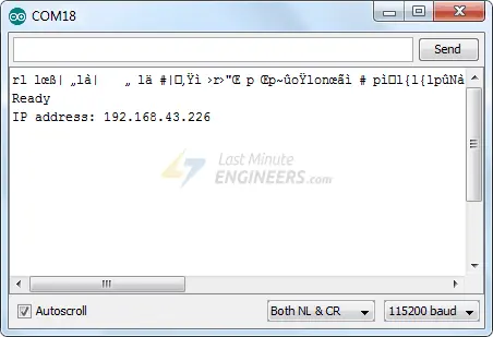
Monitor the Upload Progress: Open the Serial Monitor in the Arduino IDE at a baud rate of 115200. The ESP8266 will print the progress of the upload process.
Note the IP Address: After the upload is successful, the ESP8266 will print “Ready” along with its assigned IP address. Make a note of this IP address, as it will be needed for OTA updates.
#include <ESP8266WiFi.h>
#include <ESP8266mDNS.h>
#include <WiFiUdp.h>
#include <ArduinoOTA.h>

const char* ssid = "..........";
const char* password = "..........";

void setup() {
  Serial.begin(115200);
  Serial.println("Booting");
  WiFi.mode(WIFI_STA);
  WiFi.begin(ssid, password);
  while (WiFi.waitForConnectResult() != WL_CONNECTED) {
    Serial.println("Connection Failed! Rebooting...");
    delay(5000);
    ESP.restart();
  }

  // Port defaults to 8266
  // ArduinoOTA.setPort(8266);

  // Hostname defaults to esp8266-[ChipID]
  // ArduinoOTA.setHostname("myesp8266");

  // No authentication by default
  // ArduinoOTA.setPassword("admin");

  // Password can be set with it's md5 value as well
  // MD5(admin) = 21232f297a57a5a743894a0e4a801fc3
  // ArduinoOTA.setPasswordHash("21232f297a57a5a743894a0e4a801fc3");

  ArduinoOTA.onStart([]() {
    String type;
    if (ArduinoOTA.getCommand() == U_FLASH)
      type = "sketch";
    else // U_SPIFFS
      type = "filesystem";

    // NOTE: if updating SPIFFS this would be the place to unmount SPIFFS using SPIFFS.end()
    Serial.println("Start updating " + type);
  });
  ArduinoOTA.onEnd([]() {
    Serial.println("\nEnd");
  });
  ArduinoOTA.onProgress([](unsigned int progress, unsigned int total) {
    Serial.printf("Progress: %u%%\r", (progress / (total / 100)));
  });
  ArduinoOTA.onError([](ota_error_t error) {
    Serial.printf("Error[%u]: ", error);
    if (error == OTA_AUTH_ERROR) Serial.println("Auth Failed");
    else if (error == OTA_BEGIN_ERROR) Serial.println("Begin Failed");
    else if (error == OTA_CONNECT_ERROR) Serial.println("Connect Failed");
    else if (error == OTA_RECEIVE_ERROR) Serial.println("Receive Failed");
    else if (error == OTA_END_ERROR) Serial.println("End Failed");
  });
  ArduinoOTA.begin();
  Serial.println("Ready");
  Serial.print("IP address: ");
  Serial.println(WiFi.localIP());
}

void loop() {
  ArduinoOTA.handle();
}
To confirm that everything is functioning correctly, open the Serial Monitor and press the RST (Reset) button on the ESP8266. If all is well, you should see the dynamic IP address assigned by your router. Your ESP8266 is now ready to receive updates over-the-air. This step is only required once to set up OTA capability for future wireless updates.
Step 3: Uploading New Sketch Over-The-Air
Now, let’s proceed with uploading a new sketch wirelessly using Over-The-Air (OTA) capability.
Important Note: For OTA updates to work, you must include the OTA code in every sketch you upload. Failure to do so will result in the loss of OTA capability, and you won’t be able to perform future updates over-the-air. It is advisable to modify the preceding code, which included the Basic OTA example, to incorporate your new code.
Below, we’ll demonstrate an example of adding a simple Blink sketch to the Basic OTA code. Don’t forget to modify the SSID and password variables with your Wi-Fi network credentials.
#include <ESP8266WiFi.h>
#include <ESP8266mDNS.h>
#include <WiFiUdp.h>
#include <ArduinoOTA.h>

const char* ssid = "..........";
const char* password = "..........";

//variabls for blinking an LED with Millis
const int led = D0; // ESP8266 Pin to which onboard LED is connected
unsigned long previousMillis = 0;  // will store last time LED was updated
const long interval = 1000;  // interval at which to blink (milliseconds)
int ledState = LOW;  // ledState used to set the LED
void setup() {
pinMode(led, OUTPUT);

  Serial.begin(115200);
  Serial.println("Booting");
  WiFi.mode(WIFI_STA);
  WiFi.begin(ssid, password);
  while (WiFi.waitForConnectResult() != WL_CONNECTED) {
    Serial.println("Connection Failed! Rebooting...");
    delay(5000);
    ESP.restart();
  }

  // Port defaults to 8266
  // ArduinoOTA.setPort(8266);

  // Hostname defaults to esp8266-[ChipID]
  // ArduinoOTA.setHostname("myesp8266");

  // No authentication by default
  // ArduinoOTA.setPassword("admin");

  // Password can be set with it's md5 value as well
  // MD5(admin) = 21232f297a57a5a743894a0e4a801fc3
  // ArduinoOTA.setPasswordHash("21232f297a57a5a743894a0e4a801fc3");

  ArduinoOTA.onStart([]() {
    String type;
    if (ArduinoOTA.getCommand() == U_FLASH)
      type = "sketch";
    else // U_SPIFFS
      type = "filesystem";

    // NOTE: if updating SPIFFS this would be the place to unmount SPIFFS using SPIFFS.end()
    Serial.println("Start updating " + type);
  });
  ArduinoOTA.onEnd([]() {
    Serial.println("\nEnd");
  });
  ArduinoOTA.onProgress([](unsigned int progress, unsigned int total) {
    Serial.printf("Progress: %u%%\r", (progress / (total / 100)));
  });
  ArduinoOTA.onError([](ota_error_t error) {
    Serial.printf("Error[%u]: ", error);
    if (error == OTA_AUTH_ERROR) Serial.println("Auth Failed");
    else if (error == OTA_BEGIN_ERROR) Serial.println("Begin Failed");
    else if (error == OTA_CONNECT_ERROR) Serial.println("Connect Failed");
    else if (error == OTA_RECEIVE_ERROR) Serial.println("Receive Failed");
    else if (error == OTA_END_ERROR) Serial.println("End Failed");
  });
  ArduinoOTA.begin();
  Serial.println("Ready");
  Serial.print("IP address: ");
  Serial.println(WiFi.localIP());
}

void loop() {
  ArduinoOTA.handle();

//loop to blink without delay
  unsigned long currentMillis = millis();
  if (currentMillis - previousMillis >= interval) {
  // save the last time you blinked the LED
  previousMillis = currentMillis;
  // if the LED is off turn it on and vice-versa:
  ledState = not(ledState);
  // set the LED with the ledState of the variable:
  digitalWrite(led,  ledState);
  }
}
Please take note that we have replaced the “delay()” function with a “Millis” based approach for LED blinking. The use of the “delay()” function can pause the program, which might cause the ESP8266 to miss OTA requests while waiting for the delay to finish.
After you have copied the modified sketch into your Arduino IDE, follow these steps:
Go to “Tools” and select “Port” in the Arduino IDE.
Search for something similar to “esp8266-xxxxxx at your_esp_ip_address.” If you cannot find it, try restarting your IDE.
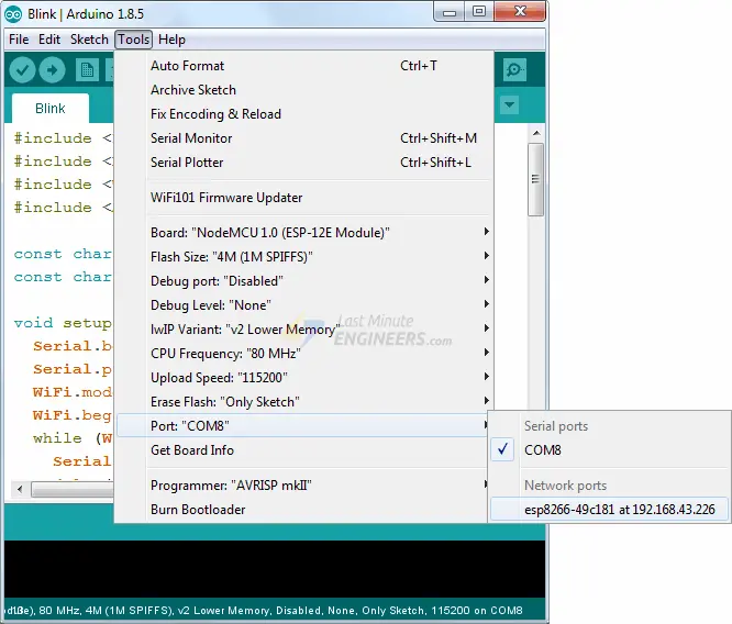
Choose the appropriate port that matches your connected ESP8266 module.
Click the “Upload” button to initiate the OTA process. The new sketch will be wirelessly uploaded in just a few seconds.

Once the upload is successful, the onboard LED should start blinking according to the updated sketch.
Congratulations! You have now successfully performed an over-the-air upload of a new sketch to your ESP8266 using OTA capability.
Related article
- Step-by-Step Tutorial: Installing ESP8266 Board in Arduino IDE
- Mastering ESP8266 GPIO Interrupts: Arduino IDE Configuration Tips
- Complete ESP8266 Pinout Reference: Simplify Your Hardware Connections


I wasn’t able to see the Network address after the initial upload and not after a reboot of the computer and Arduino IDE 2.2.1