

Whether you refer to them as individually addressable RGB LEDs, WS2812B, or NeoPixels, their immense popularity is undeniable, making them an essential component for any project requiring luminous and dynamic effects.
While writing code to govern addressable LEDs is not particularly challenging, what if your objective is simply to imbue your living space or workplace with ambient lighting, controllable effortlessly from your smartphone? Presently, the premier solution, without question, is WLED—an exceptional, free, feature-laden, open-source mobile application that empowers users with comprehensive control over an extensive array of RGB LEDs.
The WLED app streamlines the process of managing individually addressable LEDs, making it more straightforward, convenient, and, most importantly, enjoyable. This application is simply too remarkable to overlook.
This tutorial will elucidate the procedure for installing WLED on an ESP8266 board and employing it to regulate a sequence of addressable LEDs.
Parts Required
Installing WLED on an ESP8266 Board
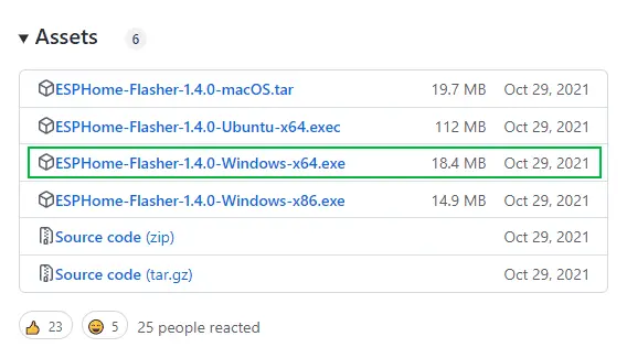
Begin by downloading the ESPHome-Flasher tool. Visit the ESPHome-Flasher GitHub page in your browser, locate the installer compatible with your operating system, and download it.
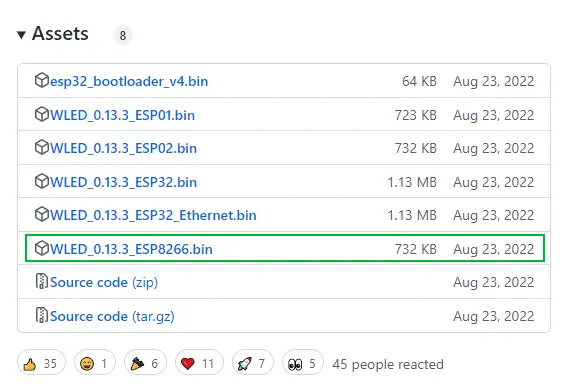
Next, acquire the WLED compiled binary. Head to the WLED GitHub page and download the WLED_0.x.x_ESP8266.bin file.
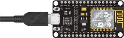
Connect your ESP8266 board to your computer using a USB cable, ensuring that the cable supports data transfer.
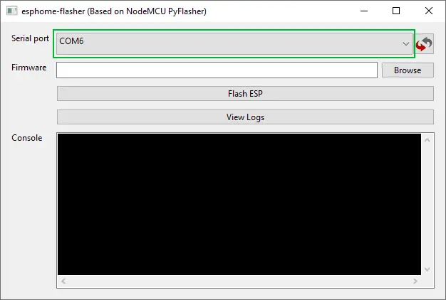
Launch the ESPHome-Flasher tool.
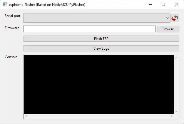
Select the COM port corresponding to your ESP8266 connection. If the serial port dropdown is empty, update your USB-to-serial drivers or verify that your USB cable supports data transfer.
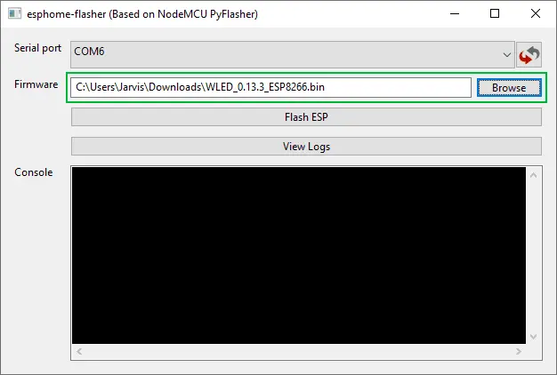
Click ‘Browse’ and choose the WLED binary file you downloaded earlier.
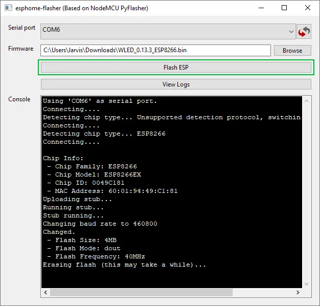
Initiate the flashing process by clicking ‘Flash ESP’. It should complete within a few minutes.
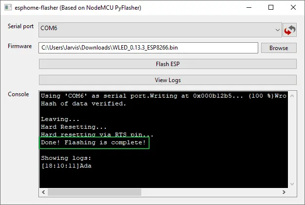
Once the message “Done! Flashing is complete!” appears, you can close the program.
Locate the Network icon on the taskbar and find a new wireless access point named WLED-AP.
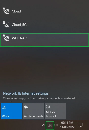
Connect to WLED-AP and input ‘wled1234’ when prompted for a password.
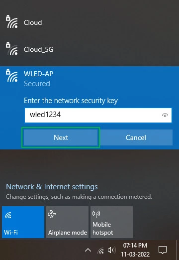
After connecting, your default browser will automatically open and load the WLED home page. If not, manually navigate to http://4.3.2.1.
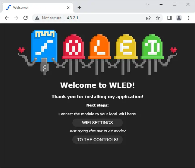
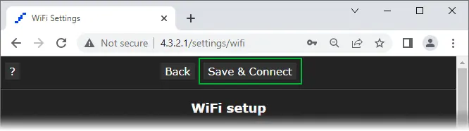
Access WIFI Settings to configure your network name, password, and mDNS address.

Customize the Network Name, Network Password, and mDNS address. For instance, set the mDNS address to http://mylights.local/.
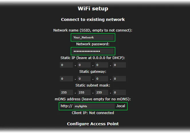
Save your changes and connect. Your ESP8266 will reboot and join your WiFi network. Consider resetting your ESP8266 using the RST button for good measure.
Reconnect to your home network.
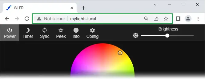
Finally, access the WLED User Interface (UI) by navigating to your mDNS address, such as http://mylights.local/.
Exploring the WLED User Interface (UI)
Initially, navigating WLED’s UI might feel daunting, but once you grasp its structure, it becomes intuitive. The UI comprises five primary sections:
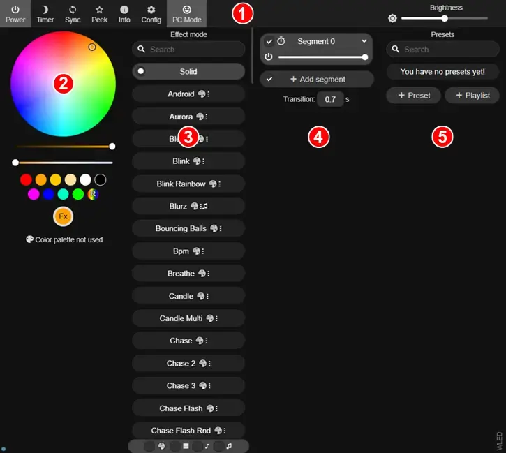
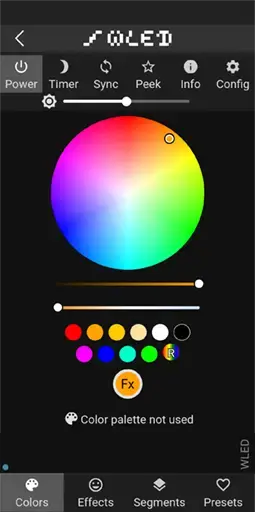
- Configuration: This area hosts buttons for key functions like Power (to switch lights on/off), Timer (for scheduling light operations), Sync (to synchronize multiple WLED devices), Peek (for previewing light animations), Config (for adjusting LED count and GPIO port settings), and a Brightness slider (for overall brightness control).
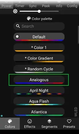
- Color Picker: Here, users can alter the color of their LEDs, whether static or animated. Moreover, scrolling down reveals diverse color palettes for use in effects.
- Effects/Animation: This section presents a library of pre-made animations for lights. Although each effect features its own color scheme, customization is effortless using the Color Picker.
- Segment: For users with extensive LED arrays or matrices, this function enables segmentation. Each segment can be assigned a distinct color, animation, or color scheme.
- Presets: In this section, users can craft presets for personalized light displays and arrange a playlist to cycle through available animations.
Setting Up WLED
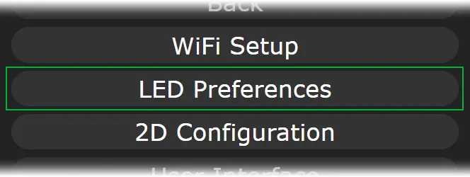
After completing the initial setup, it’s advisable to proceed to the LED Preferences screen and configure the LED lights.
Navigate to Config and choose LED Preferences.
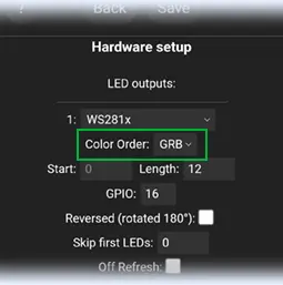
Scroll down to Hardware Setup and specify the type of LED strip you possess.

Adjust the “Length” to correspond to the number of LEDs in your setup. For instance, if you have 12 LEDs in total, set the length to 12.

Take note of the GPIO pin number, which will be used to transmit data to the LEDs. By default, GPIO2 (D4) is employed.

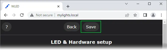
Scroll to the bottom of the page and click Save.
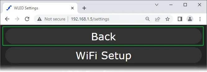
Return to the main screen by selecting Back.
Connecting a WS2812x Addressable LED Strip to an ESP8266
After configuring the WLED, disconnect the ESP8266 from the USB port and proceed with wiring the addressable LED strip.
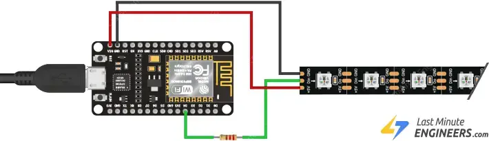
The wiring process is simple, requiring just three connections: two for power and one for data transmission.
Start by connecting the Red wire (+5V/VCC) of the LED strip to the ESP8266’s VIN pin, and the White/Yellow wire (GND) to the ESP8266’s GND pin.
Next, connect the Green wire (DIN) of the LED strip to the ESP8266’s GPIO2 (D4) pin, and include a 330 Ohm resistor in the circuit. This resistor, ideally between 220 and 470 Ohm, protects the data pin. Place it as close to the LED strip as possible.
For smaller LED setups, you can power the strip directly through the ESP8266 by connecting it to your computer using a USB cable.
However, for larger projects requiring more LEDs, USB power won’t suffice. In such cases, you’ll need to supply power to the strip from an external source. Keep in mind that each RGB LED consumes approximately 60mA (20mA per color channel) at full brightness. Therefore, for every 30 LEDs, the strip could draw up to 1.8 Amps.
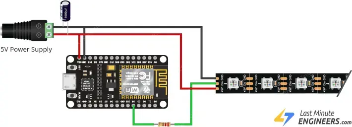
Once the wiring is complete, the LEDs should emit a soft yellow light. If not, double-check your connections before proceeding.
From this stage onward, you can control the LEDs using the WLED App.
Using the WLED Mobile App
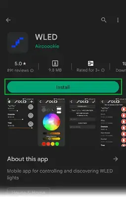
Download the WLED app from either the Google Play Store or the Apple App Store onto your smartphone or tablet.
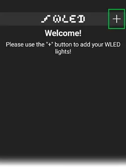
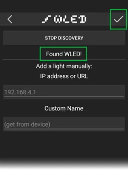
Open the app and tap on the plus icon located in the upper right corner to access the discovery page.
Tap on “Discover Lights”. This will initiate a search through your Wi-Fi network for all connected boards running WLED software.
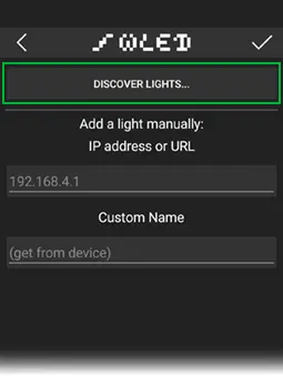
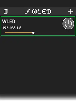
Once it displays “Found WLED!”, tap the checkmark icon in the upper-right corner. This action will return you to the home page, where you’ll find a list of all WLED devices detected on your network.
Tap on the newly discovered device to access its control panel.
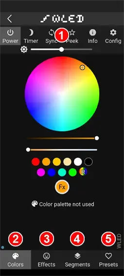
Use the color wheel to select a desired color. And there you have it—fully functional, remotely controllable addressable LEDs!
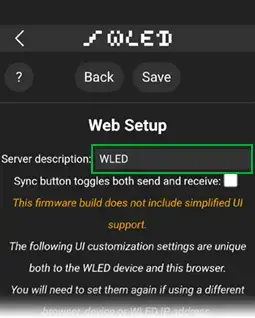
If you have multiple WLED devices, you might want to customize the displayed name in the app for easier differentiation. Navigate to Config > User Interface, enter your preferred name, and then tap Save.
Changing Effects
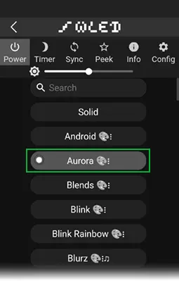
WLED provides access to more than 180 diverse effects, marking the beginning of true enjoyment.
- Go to the Effects tab and choose an effect. The LEDs will promptly respond.
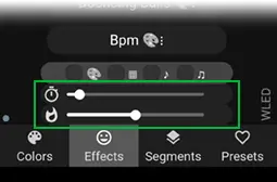
- Adjust the speed and intensity of the effect. Moving the slider further enhances both speed and intensity.
- Each effect features its unique color scheme, which you can conveniently modify in the Color Picker section. This allows you to retain the animation effect while altering the colors.
Tips and Recommendations
When setting up your configuration with ESP8266, consider the following tips and recommendations:
- ESP8266 can manage up to three LED strips simultaneously.
- While many strip types remain untested, the following have been verified to work: WS281x, SK6812 RGBW, PWM white.
- Immediately after installation, access the LED settings page to specify the LED type, pin numbers, length, and color order of your LED strips.
- To significantly increase framerate, choose an appropriate power supply for your setup and disable the WLED brightness limiter setting.
- It’s advisable to utilize two LED pins, GPIO1 (TX) and GPIO2 (D4), as they support hardware driving.
- When using GPIO1, serial debugging is deactivated. If debugging isn’t required, you can connect a strip to this pin.
- GPIO3 is the third pin on the ESP8266 that supports hardware driving. However, it consumes five times the memory per LED compared to GPIO 1 and 2, so it’s recommended for use with low LED counts (preferably <50).
- While it’s possible to use any other pin, using the bitbang method for that purpose is not recommended for reliability. It’s best to stick with GPIO 1, 2, and, if necessary, 3.
- Performance is influenced by the number of LEDs driven with the ESP8266 and the number of ESP8266 output pins used.
- For optimal performance, consider using 512 LEDs per pin with 2 outputs for a total of 1024 LEDs.
- For moderate performance, you can opt for 800 LEDs per pin with 2 outputs, totaling 1600 LEDs.
- The ESP8266 can compute approximately 15k LEDs per second (equivalent to 250 LEDs at ~60fps, 500 LEDs at ~30fps, or 1000 LEDs at ~15fps).
Related article
- ESP8266 NTP Server: Fetching Accurate Date & Time with NodeMCU
- Complete Tutorial: Setting Up I2C LCD Screen for ESP8266
- Mastering Interrupts and Timers: ESP8266 Development Guide
- ESP8266 Sensor Readings: Web Server Auto-Updates via Server-Sent Events
- Control IoT Devices: ESP8266 NodeMCU Async Web Server Tutorial


