
Those who experiment with the HC-05 Bluetooth module will inevitably need to employ a set of commands known as “AT commands.” AT commands are uncomplicated, text-based instructions prefixed with “AT” (where “AT” stands for ‘attention’). These commands share similarities with those utilized in older modem devices. By transmitting specific AT commands to the HC-05 module, you can customize its settings or retrieve fundamental information, such as its name, baud rate, PIN code, role, and more.
This guide will teach you how to configure the HC-05 AT commands, allowing you to tailor the module to meet the specific requirements of your project.
Configuring the HC-05 Module
To configure the HC-05 module, you need to enter command mode and transmit AT commands through the UART port. In command mode, any ASCII bytes you transmit are treated as commands. Once modifications are made, you must restart the module to implement the changes. The altered configuration parameters persist until you modify them again or perform a factory reset.
The default configuration for the HC-05 module is:
- Device Name: HC-05
- Role: Slave
- Passkey: 1234
- Serial Parameters:
- Baud Rate: 38400 bits/s
- Stop bit: 1 bit
- Parity bit: None
- Inquire code: 0x009e8b33
Connecting HC-05 Module to a PC
When connecting the HC-05 module to a PC, you have two options to choose from.
Option 1 involves using a USB to TTL converter, creating a direct link between the HC-05 module and your PC. This converter serves as a bridge between the USB port on your PC and the TTL-level serial signals understood by the HC-05 module.
Alternatively, you can employ an Arduino as an intermediary between the PC and the HC-05 module. In this configuration, the Arduino acts as a translator, facilitating the exchange of commands and data between the PC and the HC-05 module.
Using a USB to TTL Converter
Let’s establish a connection between your HC-05 module and your PC using a USB to TTL converter.
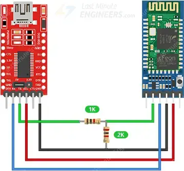
To set up the connection, apply power and wire the serial Rx and Tx pins. Connect the Tx of the HC-05 module to the converter’s RXD, the Rx to TXD, GND to GND, and VCC to 5V.
It’s crucial to note that the Rx pin on the HC-05 module is not 5V tolerant. Therefore, if you are using a USB-to-TTL converter operating at 5V I/O levels, you need to reduce the Tx signal from the converter to 3.3V. A simple method is to use a resistor divider: a 1K resistor between HC-05’s Rx and the converter’s TXD, and a 2K resistor between HC-05’s Rx and GND.
In summary, here are the connections:
| HC-05 Module | USB-to-TTL converter | Notes |
| VCC | VCC | – |
| GND | GND | – |
| TXD | Rx | – |
| RXD | Tx | Use level shifter if using 5V converter |
The image below shows the HC-05 connected to the PC using the FT232RL USB to TTL converter.
Using Arduino
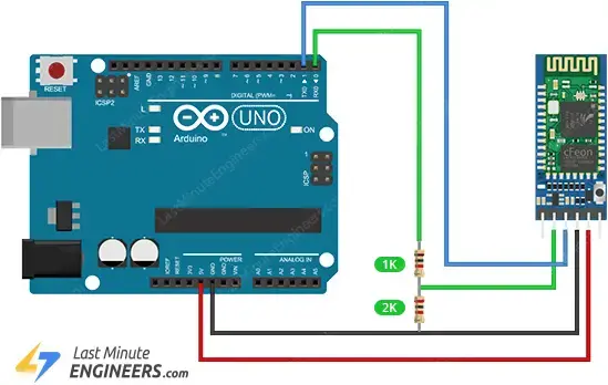
Similarly, you can establish a connection between the HC-05 Module and an Arduino. Connect the TXD of the HC-05 module to Arduino’s D1, the RXD to D0, GND to GND, and VCC to 5V.
Once again, it’s crucial to note that the Rx pin on the HC-05 module is not 5V tolerant. Therefore, if you are using a 5V microcontroller like Arduino UNO, you must lower the Tx signal from the Arduino to 3.3V using a resistor divider. Specifically, a 1K resistor between HC-05’s Rx and Arduino’s D0, along with a 2K resistor between HC-05’s Rx and GND, will function effectively.
To summarize, here are the connections:
| HC-05 Module | Arduino | Notes |
| VCC | 5V | – |
| GND | GND | – |
| TXD | D1 | – |
| RXD | D0 | Use level shifter if using 5V MCU |
The image below shows how to connect the HC-05 module to the Arduino Uno.
Parts Required
| Component Name | Buy Now |
| Arduino Uno REV3 | Amazon |
| HC-05 Bluetooth Serial Pass-through Module Wireless Serial Communication with Button for Arduino | Amazon |
| Breadboard | Amazon |
| BOJACK 1000 Pcs 25 Values Resistor Kit 1 Ohm-1M Ohm with 5% 1/4W | Amazon |
Entering AT Mode
To enter AT mode, follow these steps.
- Press and hold the push button on the HC-05 module.
- Supply power to the module.
- Release the push button now. If the onboard led starts blinking with a time difference of approximately 2 seconds, the HC-05 has successfully entered AT mode; otherwise, repeat the procedure.
Sending AT Commands
To issue AT commands, you’ll need a Windows terminal program installed on your PC capable of communicating with the HC-05 module over UART. We recommend using the “Arduino Serial Monitor” for this purpose, but there are other free alternatives (such as PuTTY, Tera Term, etc.) that you can explore.
Here’s a step-by-step guide:
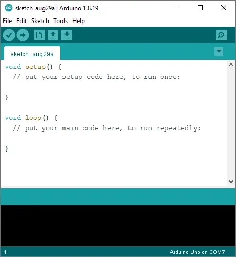
Launch the Arduino IDE.
Ensure the HC-05 module is powered up and in AT mode, indicated by the onboard LED blinking at a slow and steady rate.
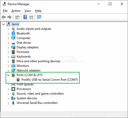
When you connect the HC-05 to your PC, it will be recognized as a COM port. Check your device manager under the “Ports (COM & LPT)” tree for the new port.
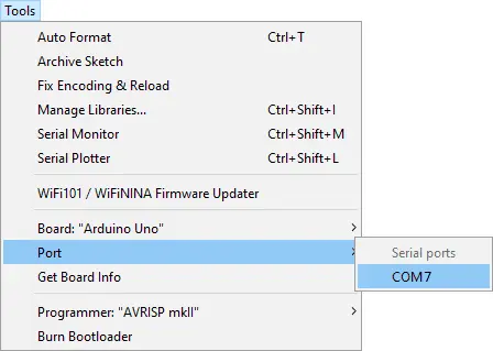
In the Arduino IDE, go to Tools > Port and select the identified COM port.
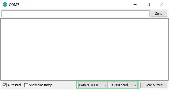
Open the Serial Monitor via Tools > Serial Monitor. Ensure the baud rate in the lower right-hand corner is set to 38400, and select the ‘Both NL and CR‘ option. This setting means that when you send commands to the HC-05, it will append a newline and return at the end.
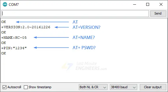
Type “AT” (without quotes) in the textbox at the top of the Serial Monitor and click the Send button. A successful communication will display “OK” as a response from the module.
You can now send various commands to gather information about your module. For instance:
- AT+VERSION? – Prints the software version.
- AT+NAME? – Prints the device’s name.
- AT+ PSWD? – Prints the passkey.
These are Read Commands. Additionally, you can send Write Commands like:
- AT+NAME=Param1 – Sets the device’s name to Param1. Note that the device name can be up to 32 bytes long and may include special characters.
HC-05 AT Commands
For your reference here’s a list of all HC-05 AT Commands.
AT
| Usage | Test |
| Response | OK |
| Parameter | – |
| Notes | – |
| Example | AT OK |
AT+RESET
| Usage | Reset the module |
| Response | OK |
| Parameter | – |
| Notes | – |
| Example | AT+RESET OK |
AT+VERSION?
| Usage | Get the software version |
| Response | +VERSION:**** OK |
| Parameter | – |
| Notes | – |
| Example | AT+VERSION? +VERSION:2.0-20100601 OK |
AT+ORGL
| Usage | Restore default status |
| Response | OK |
| Parameter | – |
| Notes | The parameter of default status: 1. Device type: 0 2. Inquire code: 0x009e8b33 3. Module work mode: Slave Mode 4. Connection mode: Connect to the Bluetooth device specified 5. Serial parameter: Baud rate: 38400 bits/s; Stop bit: 1 bit; Parity bit: None. 6. Passkey: “1234” 7. Device name: “H-C-2010-06-01” |
| Example | AT+ORGL OK |
AT+ADDR?
| Usage | Get module bluetooth address |
| Response | +ADDR:**** OK |
| Parameter | – |
| Notes | Bluetooth address will be shown as: NAP: UAP: LAP (Hexadecimal) |
| Example | AT+ADDR? +ADDR:1234:56:abcdef OK |
AT+NAME?
| Usage | Inquire device’s name | |
| Response | If Success: +NAME:**** OK | If Failure: FAIL |
| Parameter | – | |
| Notes | Default: “HC-05” | |
| Example | AT+NAME? +NAME:HC-05 OK |
AT+NAME=Param1
| Usage | Set device’s name |
| Response | OK |
| Parameter | Param1: Bluetooth device name |
| Notes | Length up to 32 bytes Supports special characters. AT+NAME=”HC-05″ is the same as AT+NAME=HC-05 |
| Example | AT+NAME=myBluetooth OK |
AT+RNAME?Param1
| Usage | Inquire remote bluetooth device’s name | |
| Response | If Success: +NAME:Param2 OK | If Failure: FAIL |
| Parameter | Param1: Remote Bluetooth device address Param2: Remote Bluetooth device name | |
| Notes | Bluetooth address will be shown as: NAP:UAP:LAP (Hexadecimal) | |
| Example | AT+RNAME?0002,72,od2224 +RNAME:Bluetooth OK |
AT+ROLE?
| Usage | Inquire module role |
| Response | +ROLE:**** OK |
| Parameter | – |
| Notes | Result is a number where: 0 -> Slave 1 -> Master 2 -> Slave-Loop |
| Example | AT+ROLE? +ROLE=0 OK |
AT+ROLE=Param1
| Usage | Set module role |
| Response | OK |
| Parameter | Param1: module role: 0 -> Slave 1 -> Master 2 -> Slave-Loop |
| Notes | Roles: Slave (Default): Passive connection Slave-Loop: Passive connection, receive the remote Bluetooth master device data and send it back to the master device Master: Inquire the near SPP Bluetooth slave device, build connection with it positively, and build up the transparent data transmission between master and slave device. |
| Example | AT+ROLE=0 OK |
AT+CLASS?
| Usage | Inquire device type | |
| Response | If Success: +CLASS:**** OK | If Failure: FAILv |
| Parameter | – | |
| Notes | Default: 0 | |
| Example | – |
AT+CLASS=Param1
| Usage | Set device type |
| Response | OK |
| Parameter | – |
| Notes | Bluetooth device type is a 32-bit parameter indicates the device type and what type can be supported. For inquiring the custom Bluetooth device from around Bluetooth devices quickly and effectively, user can set the module to be non-standard Bluetooth device type, such as 0x1F1F (Hex). |
| Example | – |
AT+IAC?
| Usage | Inquire “inquire access code” |
| Response | +IAC: **** OK |
| Parameter | – |
| Notes | Default: 9e8b33 |
| Example | AT+IAC? +IAC: 9e8b3f OK |
AT+IAC=Param1
| Usage | Set “inquire access code” | |
| Response | If Success: OK | If Failure: FAIL |
| Parameter | Param1: Inquire access code | |
| Notes | Access code is set to be GIAC type (General Inquire Access Code:0x9e8b33), and used for seeking ( or being sought by ) all the Bluetooth devices around. For inquiring (or being inquiring by) the custom Bluetooth device from around Bluetooth devices quickly and effectively, user can set the inquire access code to be the other type number (not GIAC nor LIAC), such as 9e8b3f. | |
| Example | AT+IAC=9e8b3f OK |
AT+INQM?
| Usage | Inquire inquire access mode |
| Response | +INQM:***,***,*** OK |
| Parameter | – |
| Notes | Output is in the format: Inquire access mode, the maximum of Bluetooth devices response, the maximum of limited inquiring time Default: 1, 1, 48 |
| Example | AT+INQM +INQM:1, 9, 48 OK |
AT+INQM=Param1, Param2, Param3
| Usage | Set inquire access mode | |
| Response | If Success: OK | If Failure: FAIL |
| Parameter | Param1: Inquire access mode: 0 -> Standard 1 -> RSSI Param2: The maximum of Bluetooth devices response Param3: The maximum of limited inquiring time | |
| Notes | The range of limited time: 1~48 (Corresponding time:1.28s~61.44s) | |
| Example | Set Inquire access mode such that: 1) has RSSI signal intensity indicator, 2) stop inquiring once more than 9 devices response, 3) limited time is 48*1.28=61.44s: AT+INQM=1,9,48 OK |
AT+PSWD?
| Usage | Inquire passkey |
| Response | +PSWD:**** OK |
| Parameter | – |
| Notes | Default: “1234” |
| Example | AT+PSWD? +PSWD:1234 OK |
AT+PSWD=Param1
| Usage | Set passkey |
| Response | OK |
| Parameter | Param1: Passkey |
| Notes | – |
| Example | AT+PWD=1234 (or AT+PSWD=”1234″) OK |
AT+UART?
| Usage | Inquire serial parameter |
| Response | +UART=****, ****, **** OK |
| Parameter | – |
| Notes | Output is in the format: Baud rate, Stop bit, Parity bit Default: 9600, 0, 0 |
| Example | AT+UART? +UART:115200,1,2 OK |
AT+UART=Param1, Param2, Param3
| Usage | Set serial parameter |
| Response | +UART=Param1, Param2, Param3 OK |
| Parameter | Param1: Baud rate: 4800 -> 4800 bits/s 9600 -> 9600 bits/s<br 19200 -> 19200 bits/s 38400 -> 38400 bits/s 57600 -> 57600 bits/s 115200 -> 115200 bits/s 230400 -> 230400 bits/s 460800 -> 460800 bits/s 921600 -> 921600 bits/s 1382400 -> 1382400 bits/s Param2: Stop bit: 0 -> 1 bit 1 -> 2 bits Param3: Parity bit: 0 -> None 1 -> Odd parity 2 -> Even parity |
| Notes | – |
| Example | Set baud rate to be 115200, stop bit to be 2 bits, parity bit to be even parity: AT+UART=115200,1,2 OK |
AT+CMODE?
| Usage | Inquire connection mode |
| Response | +CMODE:**** OK |
| Parameter | – |
| Notes | Result is a number where: 0 (Default) -> Connects the module to the specified Bluetooth address 1 -> Connects the module to any address 2 -> Slave-Loop |
| Example | AT+CMODE? +CMODE:2 OK |
AT+CMODE=Param1
| Usage | Set connection mode |
| Response | OK |
| Parameter | Param1: Connection mode: 0 -> Connect the module to the specified Bluetooth address. 1 -> Connect the module to any address 2 -> Slave-Loop |
| Notes | – |
| Example | AT+CMODE=2 OK |
AT+BIND?
| Usage | Inquire – bind Bluetooth address |
| Response | +BIND:**** OK |
| Parameter | – |
| Notes | Bluetooth address will be shown as: NAP: UAP:LAP(Hexadecimal) |
| Example | AT+BIND? +BIND:1234:56:abcdef OK |
AT+BIND=Param1
| Usage | Set – bind Bluetooth address |
| Response | OK |
| Parameter | Param1: Bluetooth address: needed to be bind |
| Notes | When writing the address, you must use commas rather than colons. |
| Example | AT+BIND=1234,56,abcdef OK |
AT+POLAR?
| Usage | Inquire – drive indication of LED and connection status |
| Response | +POLAR=****, **** OK |
| Parameter | – |
| Notes | Output is in the format: PI08 mode, PI09 mode Default: 1, 1 |
| Example | AT+POLAR? +POLAR=0, 1 OK |
AT+POLAR=Param1, Param2
| Usage | Set – drive indication of LED and connection status |
| Response | OK |
| Parameter | Param1: PI08 mode: 0 -> PI08 outputs low level and turn on LED 1 -> PI08 outputs high level and turn on Param2: PI09 mode: 0 -> PI09 output low level indicate successful connection 1 -> PI09 output high level indicate successful connection |
| Notes | – |
| Example | PI08 outputs low level and turn on LED, PI09 outputs high level and indicates successful connection: AT+POLAR=0, 1 OK |
AT+PIO=Param1, Param2
| Usage | Set PIO single port output |
| Response | OK |
| Parameter | Param1: PIO port number(Decimal): Param2: PIO port status: 0 -> low level 1 -> high level |
| Notes | HC-05 Bluetooth module provides the user with the ports (PI00~PI07 and PI010) which can extern another input and output ports. |
| Example | 1. PI010 port outputs high level: AT+PI0=10, 1 OK 2. PI010 port outpust low level: AT+PI0=10, 0 OK |
AT+MPIO=Param1
| Usage | Set PIO multiple port output |
| Response | OK |
| Parameter | Param1: Mask combination of PIO ports number (Decimal) |
| Notes | (1) Mask of PIO port number = (1<<port number) (2) Mask combination of PIO ports number= (PIO port number mask 1|PIO port numbermask 2|……) Example : PI02 port number mask=(1<<2) =0x004 PI010 port number mask =(1<<10)=0x400 Mask combination of PI02 and PI010 port number=(0x004|0x400)=0x404 |
| Example | 1. PI010 and PI02 ports output high level: AT+MPI0=404 OK 2. PI04 port output high level: AT+PI0=004 OK 3. PI010 port output high level: AT+PI0=400 OK 4. All ports output low level: AT+MPI0=0 OK |
AT+MPIO?
| Usage | Inquire PIO port input |
| Response | +MPIO:**** OK |
| Parameter | Param1: PIO port value (16bits) Param[0]=PI00 Param[1]=PI01 Param[2]=PI02 … Param[10]=PI010 Param[11]=PI011 |
| Notes | – |
| Example | – |
AT+IPSCAN?
| Usage | Inquire page scan and inquire scan parameter |
| Response | +IPSCAN:****, ****, ****, **** OK |
| Parameter | – |
| Notes | Output is in the format: time interval of inquiring, duration in inquiring, time interval of paging, duration in paging Default:1024,512,1024,512 |
| Example | AT+IPSCAN? +IPSCAN:1234,500,1200,250 OK |
AT+IPSCAN=Param1, Param2, Param3, Param4
| Usage | Set page scan and inquire scan parameter |
| Response | OK |
| Parameter | Param1:time interval of inquiring Param2: duration in inquiring Param3: time interval of paging Param4: duration in paging |
| Notes | – |
| Example | AT+IPSCAN=1234,500,1200,250 OK |
AT+SNIFF?
| Usage | Inquire—SNIFF energy parameter |
| Response | +SNIFF:****, ****, ****, **** OK |
| Parameter | – |
| Notes | Output is in the format: maximum time, minimum time, test time, limited time Default : 0,0,0,0 |
| Example | – |
AT+SENM?
| Usage | Inquire safe and encryption mode |
| Response | +SENM:****, **** OK |
| Parameter | – |
| Notes | Output is in the format: the value of safe mode, the value of encryption mode Default : 0,0 |
| Example | – |
AT+SENM=Param1, Param2
| Usage | Set safe and encryption mode | |
| Response | If Success: OK | If Failure: FAIL |
| Parameter | Param1: the value of safe mode: 0 -> sec_mode0+off 1 -> sec_mode1+non_secure 2 -> sec_mode2_service 3 -> sec_mode3_link 4 -> sec_mode_unknown Param2: the value of encryption mode: 0 -> hci_enc_mode_off 1 -> hci_enc_mode_pt_to_pt 2 -> hci_enc_mode_pt_to_pt_and_bcast | |
| Notes | – | |
| Example | – |
AT+RMSAD=Param1
| Usage | Delete authenticated device in the Bluetooth pair list |
| Response | OK |
| Parameter | Param1: Bluetooth device address |
| Notes | – |
| Example | AT+RMSAD=1234,56,abcdef OK | FAIL |
AT+RMAAD
| Usage | Delete all authenticated devices in the pair list |
| Response | OK |
| Parameter | – |
| Notes | – |
| Example | AT+RMAAD OK |
AT+FSAD=Param1
| Usage | Seek the authenticated device in the Bluetooth pair list | |
| Response | If Success: OK | If Failure: FAIL |
| Parameter | Param1: Bluetooth device address | |
| Notes | – | |
| Example | AT+FSAD=1234,56,abcdef OK | FAIL |
AT+ADCN?
| Usage | Get the authenticated device count from the pair list |
| Response | +ADCN:**** OK |
| Parameter | – |
| Notes | – |
| Example | AT+ADCN? +ADCN:0 OK |
AT+MRAD?
| Usage | Get the Bluetooth address of Most Recently Used Authenticated Device |
| Response | +MRAD:**** OK |
| Parameter | – |
| Notes | – |
| Example | AT+MRAD? +MRAD:0:0:0 OK |
AT+STATE?
| Usage | Get the work status of Bluetooth module |
| Response | +STATE:**** OK |
| Parameter | – |
| Notes | Result can be one of the following: “INITIALIZED” -> initialized status “READY” -> ready status “PAIRABLE” -> pairable status “PAIRED” -> paired status “INQUIRING” -> inquiring status “CONNECTING” -> connecting status “CONNECTED” -> connected status “DISCONNECTED” -> disconnected status “NUKNOW” -> unknown status |
| Example | AT+STATE? +STATE:INITIALIZED OK |
AT+INIT
| Usage | Initialize the SPP profile lib | |
| Response | If Success: OK | If Failure: FAIL |
| Parameter | – | |
| Notes | – | |
| Example | AT+INIT OK |
AT+INQM?
| Usage | Inquire Bluetooth device |
| Response | +INQ:**** +INQ:**** … OK |
| Parameter | – |
| Notes | Every result is in the form: +INQ:Bluetooth address, Device type, RSSI signal intensity |
| Example | AT+INQ +INQ:2:72:D2224,3E0104,FFBC +INQ:1234:56:0,1F1F,FFC1 +INQ:1234:56:0,1F1F,FFC0 OK |
AT+PAIR=Param1, Param2
| Usage | Set pair | |
| Response | If Success: OK | If Failure: FAIL |
| Parameter | Param1: Bluetooth address of remote device Param2: limited time of connection (second) | |
| Notes | – | |
| Example | Make pair with the remote Bluetooth device(address:1234:56:abcdef), the limited time is 20s: AT+PAIR=1234,56,abcdef,20\r\n OK |
AT+LINK=Param1
| Usage | Connect device | |
| Response | If Success: OK | If Failure: FAIL |
| Parameter | Param1: Bluetooth address of remote device | |
| Notes | – | |
| Example | Connect with the remote Bluetooth device (address: 1234:56:abcdef): AT+FSAD=1234,56,abcdef OK AT+LINK=1234,56,abcdef OK |
AT+DISC
| Usage | Disconnection |
| Response | If Successful Disconnection: +DISC:SUCCESS OK If Lose the connection: +DISC:LINK_LOSS OK If No SLC connection: +DISC:NO_SLC OK If Disconnection Timeout: +DISC:TIMEOUT OK If Disconnection Error: +DISC:ERROR OK |
| Parameter | – |
| Notes | – |
| Example | – |
AT+ENSNIFF=Param1
| Usage | Enter to energy mode |
| Response | OK |
| Parameter | Param1: Bluetooth address of device |
| Notes | – |
| Example | – |
AT+EXSNIFF=Param1
| Usage | Exit energy mode |
| Response | OK |
| Parameter | Param1: Bluetooth address of device |
| Notes | – |
| Example | – |
Related article
- Voltage Sensor Interfacing with Arduino: Step-by-Step Guide and Code
- Step-by-Step: Interfacing Multiple DS18B20 Sensors with Arduino
- Interfacing AM2320 Sensor with Arduino: Complete Tutorial
- Arduino Sound Sensor Interface: Control Devices with Clap Detection


