

In the past, people used to wait in long checkout lines at grocery stores, but now, thanks to RFID technology, those days are gone. With an RFID-based walk-through automatic checkout solution, you can simply fill up your shopping cart and walk right out the door. There’s no need to wait for a cashier to manually scan each item one by one. Instead, RFID tags attached to the items enable instant detection and ringing of every item in the cart.
When it comes to RFID-based Arduino projects, the RC522 RFID arduino reader/writer module is an excellent choice. It offers low power consumption, affordability, durability, ease of interfacing, and it is highly popular among hobbyists.
What is RFID technology and how does it work?
RFID technology is a system that comprises two primary components: a tag attached to the object to be identified and a reader responsible for reading the tag.
The reader consists of a radio frequency module and an antenna that generates a high-frequency electromagnetic field. On the other hand, the tag is typically a passive device, meaning it lacks a battery. It consists of a microchip that stores and processes information, along with an antenna for receiving and transmitting signals.
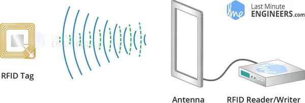
When the tag comes close to the reader, the reader generates an electromagnetic field, causing electrons to move through the tag’s antenna and power the chip.
In response, the chip sends its stored information back to the reader in the form of another radio signal, known as backscatter. The reader then detects and interprets this backscatter, sending the data to a computer or microcontroller for further processing.
Hardware Overview
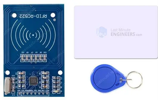
The RC522 RFID module, based on the MFRC522 IC from NXP, stands out as an affordable RFID arduino solution available online for less than four dollars. When purchased, it typically includes an RFID card tag and a key fob tag, each having 1KB of memory. An added advantage is its capability to write a tag, enabling the storage of custom messages.
The main function of the RC522 RFID reader arduino module is to generate a 13.56MHz electromagnetic field and communicate with RFID tags adhering to the ISO 14443A standard.
Communication between the reader and a microcontroller can be established via a 4-pin SPI interface, supporting data rates of up to 10 Mbps. Additionally, it offers compatibility with I2C and UART protocols.
An interesting feature of the RC522 arduino module is its ability to be programmed for generating an interrupt signal. This enables the module to notify us when a tag is in proximity, eliminating the need to continuously query the module with the question “Is there a card nearby?”.
The operating voltage of the module ranges from 2.5 to 3.3V, but the good news is that the logic pins are 5-volt tolerant. Consequently, connecting it to an Arduino or any 5V logic microcontroller can be done without requiring a logic level converter.
Technical Specifications
Here are the specifications:
| Frequency Range | 13.56 MHz ISM Band |
| Host Interface | SPI / I2C / UART |
| Operating Supply Voltage | 2.5 V to 3.3 V |
| Max. Operating Current | 13-26mA |
| Min. Current(Power down) | 10µA |
| Logic Inputs | 5V Tolerant |
| Read Range | 5 cm |
For more details, please refer below datasheet.
RC522 RFID Module Pinout
The RC522 RFID module is equipped with 8 pins, each serving specific functions for its connection to external devices. The pinout details are as follows:
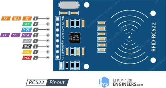
VCC: This pin is used to supply power to the module. It requires a voltage input ranging from 2.5 to 3.3 volts. It is recommended to connect this pin to the 3.3V output from the Arduino or any compatible power source. Note that connecting it to the 5V pin may lead to damage.
RST: The RST (Reset) pin serves as an input for reset and power-down operations. When this pin is set to low, the module enters power-down mode, where the oscillator is deactivated, and the input pins are disconnected from external connections. The module is reset when the signal rises.
GND: This pin is the ground connection and should be connected to the GND pin on the Arduino or the common ground of the system.
IRQ: The IRQ (Interrupt Request) pin is an interrupt line used to notify the microcontroller when an RFID tag is detected in the module’s proximity.
MISO / SCL / Tx: Depending on the selected communication interface, this pin serves different purposes. In the SPI interface, it operates as Master-In-Slave-Out (MISO), handling data transfer. For the I2C interface, it acts as the serial clock (SCL). In the UART interface, it functions as the serial data output (Tx).
MOSI (Master Out Slave In): In the SPI interface, this pin is Master-Out-Slave-In (MOSI), responsible for receiving data from the master device (e.g., Arduino) to the RC522 arduino module.
SCK (Serial Clock): The SCK pin accepts clock pulses from the SPI bus master (e.g., Arduino) in the SPI interface.
SS / SDA / Rx: This pin has different roles depending on the chosen communication interface. In the SPI interface, it acts as a signal input (SS) for selecting the device during data transfer. In the I2C interface, it functions as the serial data input (SDA). In the UART interface, it serves as the serial data input (Rx). It is often marked with a square outline for easy identification among the other pins.
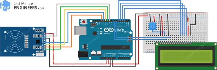
Wiring an RC522 RFID Module to an Arduino
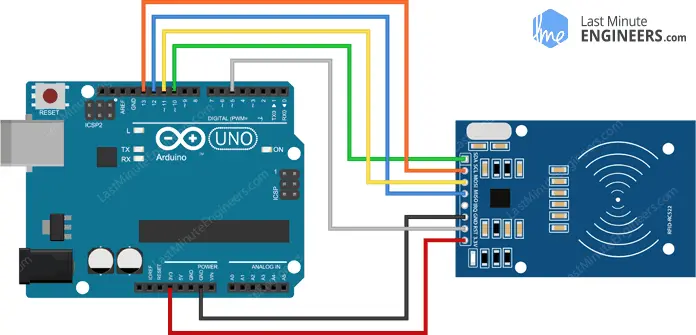
To wire an RC522 RFID module to an Arduino, follow these steps:
Connect the VCC pin on the RC522 module to the 3.3V output of the Arduino for power supply.
Connect the GND pin on the RC522 module to the GND pin on the Arduino to establish the common ground.
Connect the RST pin on the RC522 module to any available digital pin on the Arduino. In this example, it is connected to digital pin #5.
The IRQ pin on the RC522 module is not used in this setup and can be left unconnected, as the Arduino library used doesn’t support it.
For SPI communication, connect the following pins on the RC522 module to the corresponding hardware SPI pins on the Arduino:
- Connect the SCK (Serial Clock) pin on the RC522 module to digital pin 13 on the Arduino.
- Connect the MISO (Master-In-Slave-Out) pin on the RC522 module to digital pin 12 on the Arduino.
- Connect the MOSI (Master-Out-Slave-In) pin on the RC522 module to digital pin 11 on the Arduino.
- Connect the SS (Slave Select) pin on the RC522 module to digital pin 10 on the Arduino.
Please note that if you are using a different Arduino board than the UNO/Nano V3.0, it is essential to refer to the official Arduino documentation to verify the hardware SPI pins on your specific Arduino model before proceeding with the connections. The table below summarizes the pin connections for your reference:
| RC522 Module Pin | Arduino Pin |
|---|---|
| VCC | 3.3V |
| GND | GND |
| RST | Digital Pin #5 |
| IRQ | Not Connected |
| SCK | Digital Pin 13 |
| MISO | Digital Pin 12 |
| MOSI | Digital Pin 11 |
| SS | Digital Pin 10 |
Parts Required
| Component Name | Buy Now |
| Arduino Uno REV3 | Amazon |
| RFID Kit – Mifare RC522 RF IC Card Sensor Module | Amazon |
| I2C 1602 LCD Display Module | Amazon |
| Breadboard | Amazon |
| BOJACK 1000 Pcs 25 Values Resistor Kit 1 Ohm-1M Ohm with 5% 1/4W | Amazon |
Installing the Library
Interacting with an RC522 RFID module involves some complex tasks, but fortunately, there’s a convenient solution available in the form of the RFID MFRC522 library. This library simplifies the process of reading and writing RFID tags, making it easier for us to work with the module.
However, please note that the MFRC522 library is not pre-installed in the Arduino IDE. Therefore, you need to install it before you can use it in your projects.
To install the library, follow these steps:
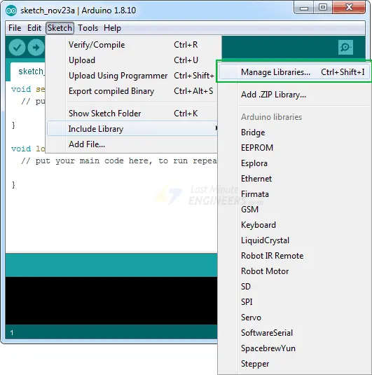
Open the Arduino IDE and go to “Sketch” in the top menu.
From the drop-down menu, select “Include Library” and then click on “Manage Libraries…”.
The Library Manager will open, and it will download the library index and update the list of installed libraries.
In the search bar of the Library Manager, type ‘mfrc522’ to filter the libraries.
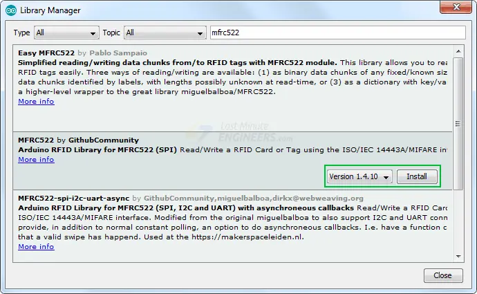
Look for the library developed by GithubCommunity, which is the official MFRC522 library.
Click on the entry corresponding to the RFID MFRC522 library, and then click the “Install” button.
Once the installation process is complete, you will be able to use the MFRC522 library in your Arduino sketches for seamless communication with the RC522 RFID module.
Arduino Code – Reading an RFID Tag
Once you have successfully installed the MFRC522 library, you can proceed with reading an RFID tag using the RC522 arduino module. Follow these steps:
Open the Examples submenu in the Arduino IDE and select MFRC522 > DumpInfo example sketch.
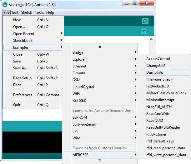
The DumpInfo sketch is designed to read the RFID tag and display the information stored within it. This feature can be quite helpful when testing new RFID tags.
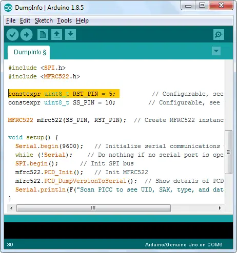
At the beginning of the sketch, ensure that the RST_PIN is initialized correctly. In our case, we are using digital pin #5, so modify the code accordingly by setting it to 5.
Upload the modified sketch to your Arduino board and then open the Serial Monitor in the Arduino IDE. Keep the RFID tag close to the RC522 arduino module and avoid moving it until all the information is displayed.
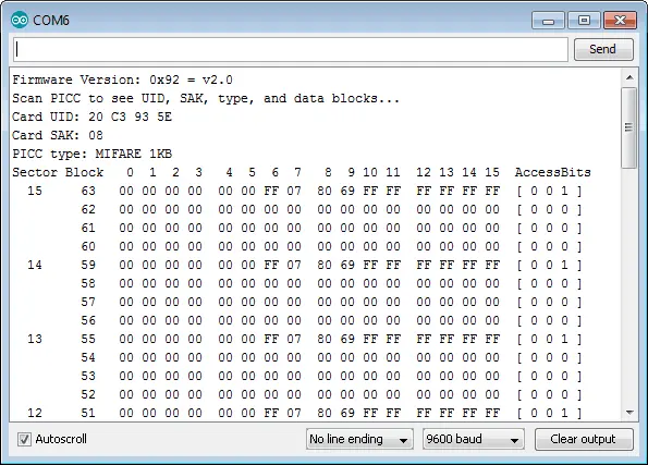
The Serial Monitor will show various details about the RFID tag, including its Unique ID (UID), memory size, and the entire 1K memory content.
By following these steps, you will be able to read and retrieve valuable information from RFID tags using the RC522 RFID module and the DumpInfo sketch. This process can be extremely useful for understanding the characteristics of different RFID tags before implementing them in your projects.
MIFARE Classic 1K Memory Layout
The MIFARE Classic 1K memory layout is organized as follows:
The memory is partitioned into 16 sectors, each identified by a number from 0 to 15. Each sector is further divided into 4 blocks, designated as blocks 0 to 3. Each block has the capacity to hold 16 bytes of data, numbered from 0 to 15.
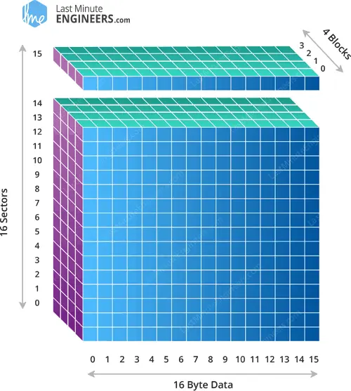
In summary, the total memory capacity can be calculated as:
16 sectors x 4 blocks x 16 bytes of data = 1024 bytes = 1K memory
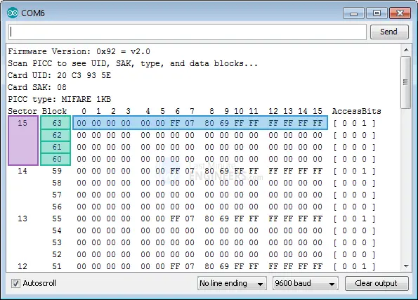
The last block within every sector is referred to as the “Sector Trailer.” It contains critical information called “Access Bits” that control the read and write access to the other blocks within the same sector. Consequently, only 3 blocks of each sector (Blocks #0, #1, and #2) are available for actual data storage, providing a maximum of 48 bytes of usable space per sector.
Notably, Block #0 of Sector #0 is known as the “Manufacturer Block.” This particular block holds essential IC Manufacturer data and the Unique Identifier (UID) of the MIFARE Classic tag.
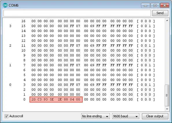
Making changes or overwriting the content of the Manufacturer Block can be extremely risky and may permanently lock the card, making it unusable. It is vital to exercise extreme caution when dealing with this block to avoid causing irreversible damage.
RFID Arduino Code – Writing an RFID Tag
Once you have successfully read an RFID tag, you can proceed with the next experiment, which involves writing custom data to an RFID tag. Below is the sketch that demonstrates this process. Before we delve into the details, try uploading the sketch to your Arduino.
#include <SPI.h> //include the SPI bus library
#include <MFRC522.h> //include the RFID reader library
#define SS_PIN 10 //slave select pin
#define RST_PIN 5 //reset pin
MFRC522 mfrc522(SS_PIN, RST_PIN); // instatiate a MFRC522 reader object.
MFRC522::MIFARE_Key key; //create a MIFARE_Key struct named 'key', which will hold the card information
//this is the block number we will write into and then read.
int block=2;
byte blockcontent[16] = {"Last-Minute-Engg"}; //an array with 16 bytes to be written into one of the 64 card blocks is defined
//byte blockcontent[16] = {0,0,0,0,0,0,0,0,0,0,0,0,0,0,0,0}; //all zeros. This can be used to delete a block.
//This array is used for reading out a block.
byte readbackblock[18];
void setup()
{
Serial.begin(9600); // Initialize serial communications with the PC
SPI.begin(); // Init SPI bus
mfrc522.PCD_Init(); // Init MFRC522 card (in case you wonder what PCD means: proximity coupling device)
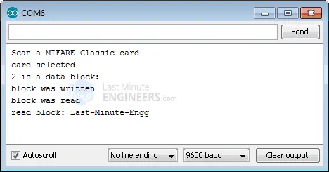
Serial.println("Scan a MIFARE Classic card");
// Prepare the security key for the read and write functions.
for (byte i = 0; i < 6; i++) {
key.keyByte[i] = 0xFF; //keyByte is defined in the "MIFARE_Key" 'struct' definition in the .h file of the library
}
}
void loop()
{
// Look for new cards
if ( ! mfrc522.PICC_IsNewCardPresent()) {
return;
}
// Select one of the cards
if ( ! mfrc522.PICC_ReadCardSerial())
{
return;
}
Serial.println("card selected");
//the blockcontent array is written into the card block
writeBlock(block, blockcontent);
//read the block back
readBlock(block, readbackblock);
//uncomment below line if you want to see the entire 1k memory with the block written into it.
//mfrc522.PICC_DumpToSerial(&(mfrc522.uid));
//print the block contents
Serial.print("read block: ");
for (int j=0 ; j<16 ; j++)
{
Serial.write (readbackblock[j]);
}
Serial.println("");
}
//Write specific block
int writeBlock(int blockNumber, byte arrayAddress[])
{
//this makes sure that we only write into data blocks. Every 4th block is a trailer block for the access/security info.
int largestModulo4Number=blockNumber/4*4;
int trailerBlock=largestModulo4Number+3;//determine trailer block for the sector
if (blockNumber > 2 && (blockNumber+1)%4 == 0){Serial.print(blockNumber);Serial.println(" is a trailer block:");return 2;}
Serial.print(blockNumber);
Serial.println(" is a data block:");
//authentication of the desired block for access
byte status = mfrc522.PCD_Authenticate(MFRC522::PICC_CMD_MF_AUTH_KEY_A, trailerBlock, &key, &(mfrc522.uid));
if (status != MFRC522::STATUS_OK) {
Serial.print("PCD_Authenticate() failed: ");
Serial.println(mfrc522.GetStatusCodeName(status));
return 3;//return "3" as error message
}
//writing the block
status = mfrc522.MIFARE_Write(blockNumber, arrayAddress, 16);
//status = mfrc522.MIFARE_Write(9, value1Block, 16);
if (status != MFRC522::STATUS_OK) {
Serial.print("MIFARE_Write() failed: ");
Serial.println(mfrc522.GetStatusCodeName(status));
return 4;//return "4" as error message
}
Serial.println("block was written");
}
//Read specific block
int readBlock(int blockNumber, byte arrayAddress[])
{
int largestModulo4Number=blockNumber/4*4;
int trailerBlock=largestModulo4Number+3;//determine trailer block for the sector
//authentication of the desired block for access
byte status = mfrc522.PCD_Authenticate(MFRC522::PICC_CMD_MF_AUTH_KEY_A, trailerBlock, &key, &(mfrc522.uid));
if (status != MFRC522::STATUS_OK) {
Serial.print("PCD_Authenticate() failed (read): ");
Serial.println(mfrc522.GetStatusCodeName(status));
return 3;//return "3" as error message
}
//reading a block
byte buffersize = 18;//we need to define a variable with the read buffer size, since the MIFARE_Read method below needs a pointer to the variable that contains the size...
status = mfrc522.MIFARE_Read(blockNumber, arrayAddress, &buffersize);//&buffersize is a pointer to the buffersize variable; MIFARE_Read requires a pointer instead of just a number
if (status != MFRC522::STATUS_OK) {
Serial.print("MIFARE_read() failed: ");
Serial.println(mfrc522.GetStatusCodeName(status));
return 4;//return "4" as error message
}
Serial.println("block was read");
}
The output on the serial monitor will look something like this.
Code Explanation:
The code includes the required libraries, “SPI.h” for SPI communication and “MFRC522.h” for the RFID reader arduino module. It defines two constants, “SS_PIN” and “RST_PIN,” representing the Slave Select and Reset pins connected to the RC522 arduino module.
The code creates an MFRC522 reader object named “mfrc522” and a MIFARE_Key struct named “key” to hold the card information.
#include <SPI.h>//include the SPI bus library
#include <MFRC522.h>//include the RFID reader library

#define SS_PIN 10  //slave select pin
#define RST_PIN 5  //reset pin
MFRC522 mfrc522(SS_PIN, RST_PIN);        // instatiate a MFRC522 reader object.
MFRC522::MIFARE_Key key;//create a MIFARE_Key struct named 'key', which will hold the card information
The code defines the block number “block” (Sector #0, Block #2) where it will write data. It also sets up an array “blockcontent” of 16 bytes to hold the custom message that will be written to the block.
//this is the block number we will write into and then read.
int block=2;

byte blockcontent[16] = {"Last-Minute-Engg"};  //an array with 16 bytes to be written into one of the 64 card blocks is defined
//byte blockcontent[16] = {0,0,0,0,0,0,0,0,0,0,0,0,0,0,0,0};  //all zeros. This can be used to delete a block.
An array “readbackblock” of 18 bytes is defined to store the content of the block that will be read back.
//This array is used for reading out a block.
byte readbackblock[18];
In the setup function, the code initializes serial communication with the PC, the SPI bus, and the MFRC522 card. It also prepares the security key for read and write functions by setting all six bytes of the “key” to 0xFF.
Serial.begin(9600);        // Initialize serial communications with the PC
SPI.begin();               // Init SPI bus
mfrc522.PCD_Init();        // Init MFRC522 card (in case you wonder what PCD means: proximity coupling device)
Serial.println("Scan a MIFARE Classic card");

// Prepare the security key for the read and write functions.
for (byte i = 0; i < 6; i++) {
   key.keyByte[i] = 0xFF;  //keyByte is defined in the "MIFARE_Key" 'struct' definition in the .h file of the library
}
The main part of the code lies in the loop function, which continuously runs.
The code checks for a new RFID card’s presence using “mfrc522.PICC_IsNewCardPresent()” and selects the card for further operations using mfrc522.PICC_ReadCardSerial().
// Look for new cards
  if ( ! mfrc522.PICC_IsNewCardPresent()) {
    return;
  }

  // Select one of the cards
  if ( ! mfrc522.PICC_ReadCardSerial())
  {
    return;
  }
  Serial.println("card selected");
The custom function writeBlock() is called to write the “blockcontent” array to the specified block on the RFID card.
//the blockcontent array is written into the card block
writeBlock(block, blockcontent);
The custom function readBlock() is called to read the content of the written block into the “readbackblock” array.
//read the block back
readBlock(block, readbackblock);
//uncomment below line if you want to see the entire 1k memory with the block written into it.
//mfrc522.PICC_DumpToSerial(&(mfrc522.uid));
The code uses a “for” loop to print the contents of the “readbackblock” array on the serial monitor, showing the data read from the RFID tag.
//print the block contents
 Serial.print("read block: ");
 for (int j=0 ; j<16 ; j++)
 {
   Serial.write (readbackblock[j]);
 }
 Serial.println("");
In summary, this code allows an Arduino to interact with an RFID tag using the MFRC522 reader module. It reads and writes data to the RFID tag’s specific block, and then reads it back to verify successful writing. The code showcases how to use the RFID MFRC522 library to manage RFID arduino communication effectively.
Arduino Project – RFID Based Door Access Control System
In this Arduino project, we will demonstrate how to create a door access control system using a basic RC522 RFID reader arduino module.
The provided code enables the Arduino to read the unique ID of each RFID tag. If the tag’s UID matches a predefined value (master tag) stored in the Arduino’s memory, access is granted. If the tag is not recognized, access will be denied.
The system’s output will be displayed on a screen, indicating whether access is granted or denied for each scanned RFID tag.
This project can be extended to include additional functionalities, such as opening doors, activating relays, illuminating LEDs, or other customized tasks based on the RFID tag’s UID.
Before proceeding to upload the code and test the RFID tags, let’s review the wiring configuration for the project.
Feel free to experiment with the following sketch:
#include <SPI.h>
#include <MFRC522.h>
#include <LiquidCrystal.h>

#define RST_PIN 9
#define SS_PIN 10

byte readCard[4];
String MasterTag = "20C3935E";	// REPLACE this Tag ID with your Tag ID!!!
String tagID = "";

// Create instances
MFRC522 mfrc522(SS_PIN, RST_PIN);
LiquidCrystal lcd(7, 6, 5, 4, 3, 2); //Parameters: (rs, enable, d4, d5, d6, d7)

void setup()
{
  // Initiating
  SPI.begin(); // SPI bus
  mfrc522.PCD_Init(); // MFRC522
  lcd.begin(16, 2); // LCD screen

  lcd.clear();
  lcd.print(" Access Control ");
  lcd.setCursor(0, 1);
  lcd.print("Scan Your Card>>");
}

void loop()
{

  //Wait until new tag is available
  while (getID())
  {
    lcd.clear();
    lcd.setCursor(0, 0);

    if (tagID == MasterTag)
    {

      lcd.print(" Access Granted!");
      // You can write any code here like opening doors, switching on a relay, lighting up an LED, or anything else you can think of.
    }
    else
    {
      lcd.print(" Access Denied!");
    }

      lcd.setCursor(0, 1);
      lcd.print(" ID : ");
      lcd.print(tagID);

    delay(2000);

    lcd.clear();
    lcd.print(" Access Control ");
    lcd.setCursor(0, 1);
    lcd.print("Scan Your Card>>");
  }
}

//Read new tag if available
boolean getID()
{
  // Getting ready for Reading PICCs
  if ( ! mfrc522.PICC_IsNewCardPresent()) { //If a new PICC placed to RFID reader continue
  return false;
  }
  if ( ! mfrc522.PICC_ReadCardSerial()) { //Since a PICC placed get Serial and continue
  return false;
  }
  tagID = "";
  for ( uint8_t i = 0; i < 4; i++) { // The MIFARE PICCs that we use have 4 byte UID
  //readCard[i] = mfrc522.uid.uidByte[i];
  tagID.concat(String(mfrc522.uid.uidByte[i], HEX)); // Adds the 4 bytes in a single String variable
  }
  tagID.toUpperCase();
  mfrc522.PICC_HaltA(); // Stop reading
  return true;
}
Code Explanation:
The program is straightforward and aims to implement a door access control system using the RC522 RFID reader module. Let’s break down the code step by step:
We begin by including the necessary libraries for the project, which are SPI.h, MFRC522.h, and LiquidCrystal.h. Then, we define the Arduino pins for the RC522 module using RST_PIN (reset pin) and SS_PIN (slave select pin). Additionally, we create variables to store the read card data, the master tag ID (replace this with your own tag ID), and a variable to hold the tag ID read by the system.
#include <SPI.h>
#include <MFRC522.h>
#include <LiquidCrystal.h>

#define RST_PIN 9
#define SS_PIN 10

byte readCard[4];
String MasterTag = "20C3935E";	// REPLACE this Tag ID with your Tag ID!!!
String tagID = "";

// Create instances
MFRC522 mfrc522(SS_PIN, RST_PIN);
LiquidCrystal lcd(7, 6, 5, 4, 3, 2); //Parameters: (rs, enable, d4, d5, d6, d7)
In the setup function, we initialize the SPI interface and the MFRC522 object. We also start the LCD screen and display a welcome message with instructions to “Scan Your Card.”
void setup()
{
  // Initiating
  SPI.begin(); // SPI bus
  mfrc522.PCD_Init(); // MFRC522
  lcd.begin(16, 2); // LCD screen

  lcd.clear();
  lcd.print(" Access Control ");
  lcd.setCursor(0, 1);
  lcd.print("Scan Your Card>>");
}
The loop function is the core of the project. It continuously checks if a new RFID tag is scanned by calling the custom function getID(). If a new tag is present, it checks whether the scanned tag’s ID matches the master tag ID. If they match, “Access Granted!” is displayed on the LCD, and you can customize additional actions here (e.g., opening doors, activating relays, etc.). If the tag is unknown or does not match the master tag ID, “Access Denied!” is displayed.
void loop()
{

  //Wait until new tag is available
  while (getID())
  {
    lcd.clear();
    lcd.setCursor(0, 0);

    if (tagID == MasterTag)
    {

      lcd.print(" Access Granted!");
      // You can write any code here like opening doors, switching on a relay, lighting up an LED, or anything else you can think of.
    }
    else
    {
      lcd.print(" Access Denied!");
    }

      lcd.setCursor(0, 1);
      lcd.print(" ID : ");
      lcd.print(tagID);

    delay(2000);

    lcd.clear();
    lcd.print(" Access Control ");
    lcd.setCursor(0, 1);
    lcd.print("Scan Your Card>>");
  }
}
This function is crucial for reading the RFID tag data. It checks if a new RFID tag is available for reading, and if so, it reads the tag’s UID and converts it into a string format. The function then stops reading the tag and returns “true” to indicate a successful tag read.
boolean getID()
{
  // Getting ready for Reading PICCs
  if ( ! mfrc522.PICC_IsNewCardPresent()) { //If a new PICC placed to RFID reader continue
  return false;
  }
  if ( ! mfrc522.PICC_ReadCardSerial()) { //Since a PICC placed get Serial and continue
  return false;
  }
  tagID = "";
  for ( uint8_t i = 0; i < 4; i++) { // The MIFARE PICCs that we use have 4 byte UID
  //readCard[i] = mfrc522.uid.uidByte[i];
  tagID.concat(String(mfrc522.uid.uidByte[i], HEX)); // Adds the 4 bytes in a single String variable
  }
  tagID.toUpperCase();
  mfrc522.PICC_HaltA(); // Stop reading
  return true;
}
This Arduino project offers a basic implementation of an RFID-based door access control system. With this code as a foundation, you can explore and customize the system to fit various applications, making it a versatile and useful project.
Related article
- Step-by-Step Guide: Arduino Integration with I2C LCD Screen
- Arduino LCD Tutorial: How to Interface a 16×2 Character LCD Module
- Using TMP36 Temperature Sensor: Arduino Interfacing Guide
- Mastering Light Sensing: ESP32 and BH1750 Integration Guide


