

When you hear “thumb joystick,” you probably think of a game controller. While they are primarily used for gaming, thumb joysticks are also great for DIY electronics projects like controlling robots, rovers, or camera movements.
Let’s explore the joystick module and its functionality.
Hardware Overview
If you’re familiar with the PS2 (PlayStation 2) controller, you’ll notice this joystick closely resembles the one from that device. It features a self-centering spring mechanism, meaning it returns to the center when released. The joystick has a comfortable cup-shaped knob that feels like a thumb-stick.
Potentiometers
A joystick works by translating its position along two axes — the X-axis (left to right) and the Y-axis (up and down) — into an electrical signal that a microcontroller can read. This is done using two 5K potentiometers (one for each axis) connected by a gimbal mechanism that separates horizontal and vertical movements.
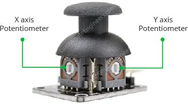
The two gray boxes on either side of the joystick are these potentiometers. As you move the joystick, each potentiometer detects movement in one specific direction. We’ll discuss their operation in more detail later.
Momentary Pushbutton Switch
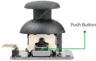
This joystick also includes a momentary pushbutton switch (a small black box on one side). When you press the joystick knob, a lever pushes down on the switch, which activates regardless of the joystick’s position.
How Does the Thumb Joystick Module Work?
It’s fascinating how a joystick can capture every subtle movement of your fingertips. This capability is due to its design, which includes two potentiometers and a gimbal mechanism.
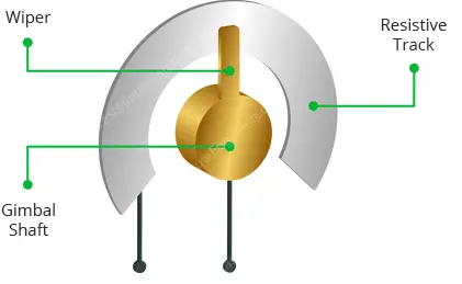
Gimbal Mechanism
When you move the joystick, a thin rod positioned between two rotatable slotted shafts (gimbal) shifts. One shaft allows for movement along the X-axis (left and right), and the other allows for movement along the Y-axis (up and down).
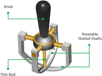
- Moving the joystick back and forth pivots the Y-axis shaft.
- Moving it left to right pivots the X-axis shaft.
- Diagonal movements cause both shafts to pivot.
Each shaft connects to a potentiometer, so moving the shaft rotates the corresponding potentiometer’s wiper. Pushing the knob all the way forward moves the potentiometer wiper to one end of its resistive track, and pulling it back moves it to the opposite end.
By reading these potentiometers, the joystick’s position can be determined.
Reading Analog Values from the Joystick
The joystick outputs an analog signal with a voltage ranging from 0 to 5V. Moving the joystick along the X-axis from one extreme to the other changes the X output from 0 to 5V, and the same occurs for the Y-axis. When the joystick is centered, the output voltage is about half of VCC, or 2.5V.
This output voltage can be fed into an ADC (Analog-to-Digital Converter) on a microcontroller to determine the joystick’s physical position.
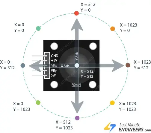
Since the Arduino board has a 10-bit ADC resolution, the values on each analog channel (axis) can range from 0 to 1023. Thus, moving the joystick from one extreme to the other will yield values between 0 and 1023 for the respective channel. When centered, both the vertical and horizontal channels will read approximately 512.
The figure below illustrates the X and Y axes and shows how the outputs respond when the joystick is moved in various directions.
Thumb Joystick Module Pinout
Let’s examine the pinout of the Thumb Joystick module.
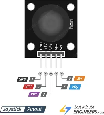
- GND: Ground pin.
- VCC: Power supply pin. Connect this to your positive supply (typically 5V or 3.3V, depending on your logic levels).
- VRx: Horizontal output voltage. Moving the joystick left to right changes the voltage from 0 to VCC. It reads approximately half of VCC when centered.
- VRy: Vertical output voltage. Moving the joystick up and down changes the voltage from 0 to VCC. It reads approximately half of VCC when centered.
- SW: Pushbutton switch output. The switch output is floating by default. A pull-up resistor is needed so that the output is LOW when the joystick knob is pressed, and HIGH otherwise. Ensure the input pin connected to the switch has an internal pull-up enabled or use an external pull-up resistor.
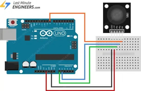
Wiring a Thumb Joystick Module to an Arduino
Now that we understand the joystick module’s pinout, let’s connect it to an Arduino.
- Connect VRx to Arduino’s analog pin A0.
- Connect VRy to Arduino’s analog pin A1.
- Connect the joystick’s SW pin to Arduino digital pin D8 to detect button presses.
- Connect the VCC pin to the 5V terminal on the Arduino.
- Connect the GND pin to the Arduino’s ground terminal.
The following table summarizes the pin connections:
| Joystick Pin | Arduino Pin |
|---|---|
| VRx | A0 |
| VRy | A1 |
| SW | D8 |
| VCC | 5V |
| GND | GND |
Parts Required
Arduino Example 1 – Reading the Joystick
Here’s a simple Arduino sketch that sets up the microcontroller to read joystick inputs and continuously print the values to the serial monitor.
// Arduino pin numbers
const int SW_pin = 8; // digital pin connected to switch output
const int X_pin = 0; // analog pin connected to X output
const int Y_pin = 1; // analog pin connected to Y output

void setup() {
  pinMode(SW_pin, INPUT);
  digitalWrite(SW_pin, HIGH);
  Serial.begin(9600);
}

void loop() {
  Serial.print("Switch:  ");
  Serial.print(digitalRead(SW_pin));
  Serial.print(" | ");
  Serial.print("X-axis: ");
  Serial.print(analogRead(X_pin));
  Serial.print(" | ");
  Serial.print("Y-axis: ");
  Serial.print(analogRead(Y_pin));
  Serial.println(" | ");
  delay(200);
}
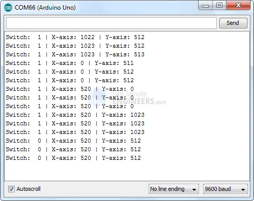
After uploading the sketch, you should see output like this on the serial monitor:
Switch: 1 | X-axis: 512 | Y-axis: 512 |
Code Explanation:
First, the joystick module’s connections are declared.
// Arduino pin numbers
const int SW_pin = 8; // digital pin connected to switch output
const int X_pin = 0; // analog pin connected to X output
const int Y_pin = 1; // analog pin connected to Y output
In the setup function, we configure the switch pin (SW_pin) as an INPUT and pull it HIGH. We also start serial communication with the PC.
  pinMode(SW_pin, INPUT);
  digitalWrite(SW_pin, HIGH);
  Serial.begin(9600);
In the loop function, we read the state of the button using digitalRead() and the positions of the X and Y axes using analogRead(). The values are then printed to the serial monitor.
  Serial.print("Switch:  ");
  Serial.print(digitalRead(SW_pin));
  Serial.print(" | ");
  Serial.print("X-axis: ");
  Serial.print(analogRead(X_pin));
  Serial.print(" | ");
  Serial.print("Y-axis: ");
  Serial.print(analogRead(Y_pin));
  Serial.println(" | ");
  delay(200);
Arduino Example 2 – Animating Joystick Movements In Processing IDE
Let’s create an Arduino project to control animations using a joystick module in the Processing IDE.
This project demonstrates how joystick movements can animate objects, and can be expanded for tasks like animating characters, surveillance, or piloting drones.
Arduino Code
This example sends the state of the pushbutton and the two analog outputs to the computer via serial communication. The corresponding Processing sketch reads this data to animate based on the joystick’s position.
The Arduino sketch is similar to the previous example but formats the output as a comma-separated string for easier parsing in Processing.
Upload the following sketch to your Arduino.
int xValue = 0 ; // read value of the X axis
int yValue = 0 ; // read value of the Y axis
int bValue = 0 ; // value of the button reading

void setup()
{
	Serial.begin(9600) ; // Open the serial port
	pinMode(8,INPUT) ; // Configure Pin 2 as input
	digitalWrite(8,HIGH);
}

void loop()
{
	// Read analog port values A0 and A1
	xValue = analogRead(A0);
	yValue = analogRead(A1);

	// Read the logic value on pin 2
	bValue = digitalRead(8);

	// We display our data separated by a comma
	Serial.print(xValue,DEC);
	Serial.print(",");
	Serial.print(yValue,DEC);
	Serial.print(",");
	Serial.print(!bValue);

	// We end with a newline character to facilitate subsequent analysis
	Serial.print("\n");

	// Small delay before the next measurement
	delay(10);
}
Processing Code
After uploading the Arduino sketch, keep the Arduino connected and run the following Processing code to animate the joystick movements.
import processing.serial.*; //import the Serial library
Serial myPort;

int x; // variable holding the value from A0
int y; // variable holding the value from A1
int b; // variable holding the value from digital pin 2
PFont f; // define the font variable
String portName;
String val;

void setup()
{
  size ( 512 , 512 ) ; // window size

  // we are opening the port
   myPort = new Serial(this, Serial.list()[0], 9600);
  myPort.bufferUntil('\n');

  // choose the font and size
  f = createFont("Arial", 16, true); // Arial, 16px, anti-aliasing
  textFont ( f, 16 ) ; // size 16px
}

// drawing loop
void draw()
{
  fill(0) ; // set the fill color to black
  clear() ; // clean the screen

  fill(255) ; // set the fill color to white

  if (b == 1) // check if the button is pressed
  {
    // draw a larger circle with specified coordinates
    ellipse(x/2,y/2, 50, 50);
  }
  else
  {
    // we draw a circle with a certain coordinates
    ellipse(x/2,y/2, 25, 25);
  }

  // we display data
  text("AnalogX="+(1023-x)+" AnalogY="+(1023-y),10,20);
}


// data support from the serial port
void serialEvent( Serial myPort)
{
  // read the data until the newline n appears
  val = myPort.readStringUntil('\n');

  if (val != null)
  {
        val = trim(val);

    // break up the decimal and new line reading
    int[] vals = int(splitTokens(val, ","));

    // we assign to variables
    x = vals[0];
    y = vals[1] ;
    b = vals[2];

  }
}
Code Explanation:
Let’s break down the code step by step.
Importing the Serial Library
First, we import the serial library to read values from the serial port.
import processing.serial.*; //import the Serial library
Serial myPort;
Declaring Variables
We then declare variables to hold the values for the x-axis, y-axis, and button state.
int x; // variable holding the value from A0
int y; // variable holding the value from A1
int b; // variable holding the value from digital pin 2
PFont f; // define the font variable
String portName;
String val;
Setup Function
In the setup function, we set the window size to 512×512 pixels. We open the first available serial port using Serial.list()[0]. If this does not work, manually select the port connected to the Arduino. We also set up the font for displaying values on the window.
  size ( 512 , 512 ) ; // window size

  // we are opening the port
   myPort = new Serial(this, Serial.list()[0], 9600);
  myPort.bufferUntil('\n');

  // choose the font and size
  f = createFont("Arial", 16, true); // Arial, 16px, anti-aliasing
  textFont ( f, 16 ) ; // size 16px
Draw Function
At the start of the draw function, the window’s background color is set to black. We then choose a white color to draw a circle representing the joystick’s position. If the pushbutton is pressed, the circle is drawn larger.
fill(0) ; // set the fill color to black
  clear() ; // clean the screen

  fill(255) ; // set the fill color to white

  if (b == 1) // check if the button is pressed
  {
    // draw a larger circle with specified coordinates
    ellipse(x/2,y/2, 50, 50);
  }
  else
  {
    // we draw a circle with a certain coordinates
    ellipse(x/2,y/2, 25, 25);
  }
The x- and y-axis values are then printed in the upper left corner of the window.
  // we display data
  text("AnalogX="+(1023-x)+" AnalogY="+(1023-y),10,20);
The custom function serialEvent(Serial myPort) helps us parse a comma-separated list of values.
void serialEvent( Serial myPort)
{
  // read the data until the newline n appears
  val = myPort.readStringUntil('\n');

  if (val != null)
  {
        val = trim(val);

    // break up the decimal and new line reading
    int[] vals = int(splitTokens(val, ","));

    // we assign to variables
    x = vals[0];
    y = vals[1] ;
    b = vals[2];

  }
}
- Control SMS & Calls with Arduino and A6 GSM Module
- Arduino and GPS: How to Interface NEO-6M Module
- Step-by-Step Guide: Interface 2 Channel Relay Channels with Arduino
- Arduino Tutorial: Interfacing a One Channel Relay Module for Control


