

In the past, cars were equipped with over 2,000 meters of cable, directly linking dashboard switches to components like headlights and taillights. As automotive technology advanced, this straightforward system became impractical. To address this, Bosch introduced the CAN bus system in 1986, which streamlined manufacturing and reduced costs. Today, CAN is the industry standard, found in a wide range of vehicles, including cars, trucks, buses, tractors, airplanes, and ships.
By learning to read and interpret CAN messages with your Arduino, you can access various car data such as coolant temperature, throttle position, vehicle speed, and engine RPM, and integrate this information into your dashboard projects.
The MCP2515 CAN Bus Interface Module is an ideal solution for adding CAN connectivity to an Arduino via the SPI interface. This tutorial will guide you through connecting the MCP2515 module to an Arduino. But first, let’s cover the basics of the CAN protocol.
Basics of CAN Bus System
The Controller Area Network (CAN bus) is a communication standard that enables devices within a vehicle to communicate with each other without needing a central computer.
To understand the CAN bus, think of it as the nervous system of a car. Just as the nervous system allows different body parts to communicate, the CAN bus allows communication between various CAN bus nodes, also known as Electronic Control Units (ECUs).
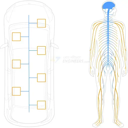
Modern vehicles contain over 70 ECUs, each handling a specific function. While these ECUs are efficient at their individual tasks, they need to exchange information. For instance, the engine control module sends the current engine speed to the instrument cluster to be displayed on the tachometer. Similarly, the driver’s door controller can signal the passenger’s door controller to operate the window.
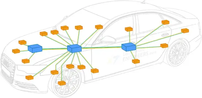
ECUs are linked in a multi-master configuration, meaning each ECU can control the bus and broadcast information, such as sensor data. All other ECUs on the CAN bus receive this broadcast and can decide whether to use or ignore the information.
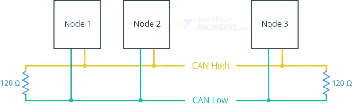
CAN Bus Topology
The CAN bus wiring harness facilitates communication, consisting of two tightly twisted wires: CAN low and CAN high. This twisting helps prevent electromagnetic interference from affecting the signals.

The ends of the cable are terminated with 120-ohm resistors to prevent signal reflection, which could disrupt communication and cause the bus to fail.
CAN Signaling
Data transmission on the CAN bus is achieved by altering the voltage levels on the wires. These voltage changes are interpreted as logic levels for network communication.
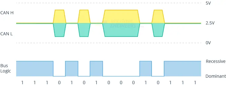
- Recessive State (logic 1): Both lines are at 2.5 volts, indicating the bus is free.
- Dominant State (logic 0): CAN high is at 3.5 volts and CAN low at 1.5 volts, indicating active transmission and that other nodes should wait.
CAN Bus Node Components
Each CAN node includes a CAN transceiver, a CAN controller, and a microcontroller:
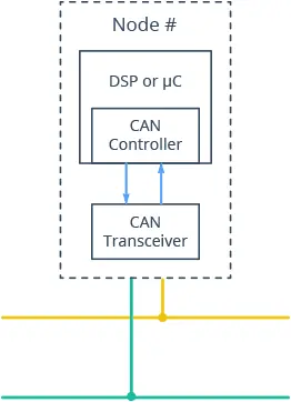
CAN Transceiver:
- Receiving: Converts bus voltage levels to readable levels for the CAN controller.
- Transmitting: Converts data from the CAN controller to bus voltage levels.
CAN Controller:
- Transmitting: Sends messages from the microcontroller serially onto the bus when it is free.
- Receiving: Collects serial bits from the bus until a full message is available, then notifies the microcontroller.
Microcontroller:
Interprets received messages and decides what to transmit. It connects to sensors, actuators, and control devices.
Standard CAN Frame
Communication over the CAN bus occurs via CAN frames. Here’s an overview of an 11-bit identifier CAN frame:
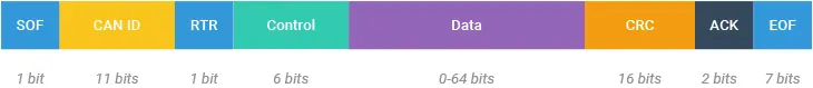
- SOF (Start of Frame): A ‘dominant 0’ signaling the start of communication.
- ID (Identifier): Indicates the message content and sender, also determining priority (lower ID means higher priority).
- RTR (Remote Transmission Request): Specifies whether a node sends or requests data.
- Control: Contains the Identifier Extension Bit (IDE) and the Data Length Code (DLC), specifying the data byte count.
- Data: Up to 8 bytes of actual information.
- CRC (Cyclic Redundancy Check): For error detection.
- ACK (Acknowledgment): Indicates receipt and correctness of the data.
- EOF (End of Frame): Marks the frame’s end.
MCP2515 Module Hardware Overview
The MCP2515 CAN Bus Interface Module is a comprehensive CAN solution featuring the MCP2515 CAN controller from Microchip and the TJA1050 High-Speed CAN transceiver from Philips. It is the optimal choice for adding CAN connectivity to an Arduino using the SPI interface.
Thanks to its reliability and robustness, the MCP2515 Module is suitable for various projects requiring dependable data transfer in noisy environments or over significant distances.
The MCP2515 CAN Controller
The MCP2515 is a standalone CAN controller compliant with the CAN specification, Version 2.0B. It can transmit and receive both standard and extended data and remote frames. The controller includes masks and filters to exclude unwanted messages, thereby reducing the workload on the host MCU.
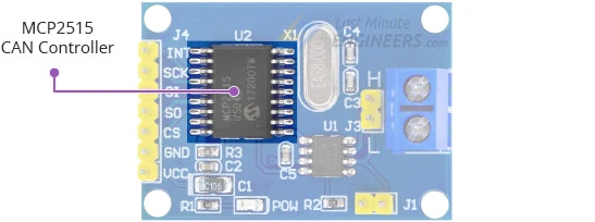
The MCP2515 also features an interrupt (INT) output pin that can trigger an MCU interrupt when a valid message is received and loaded into one of the receive buffers.
The TJA1050 CAN Transceiver
The TJA1050 transceiver interfaces between the MCP2515 CAN controller and the physical two-wire CAN bus. It meets automotive standards for high-speed (up to 1Mb/s) communication, low quiescent current, electromagnetic compatibility, and electrostatic discharge. The TJA1050 allows up to 110 nodes to be connected to the bus.
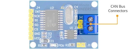
CAN Bus Connector
The module includes a 2-pole screw terminal labeled H and L for connecting the CAN bus twisted pair cable. It supports data rates up to 1Mb/s, though the maximum transfer speed depends on the bus line length: 40 meters at 1 Mb/s and 500 meters at 125 kb/s.
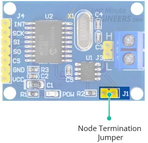
Node Termination
To prevent signal reflections, the CAN bus must be terminated with resistors at both ends. The MCP2515 Module includes a 120-ohm termination resistor and a node termination jumper. To enable the resistor, ensure the jumper is in place. If the module is at the first or last node of the CAN network, the jumper should be placed. For a middle node, the jumper should be removed.
Technical Specifications
Here are the specifications:
| Operating Voltage | 4.75 to 5.25V (based on TJA1050 requirements) |
| CAN specification | Version 2.0B at 1 Mb/s |
| Crystal Frequency | 8Mhz |
| Transmit Buffers | Three transmit buffers with prioritization and abort features |
| Receive Buffers | Two receive buffers with prioritized message storage |
| Message Filters | Six 29-bit filters |
| Masks | Two 29-bit masks |
| Interrupt Outputs | One interrupt with selectable enables |
| Interface | High-Speed SPI (10 MHz) |
For more information about the MCP2515 CAN controller, please refer to the datasheet below.
For more information about the TJA1050 CAN transceiver, please refer to the datasheet below.
MCP2515 Module Pinout
Let’s examine the pinout of the MCP2515 module.
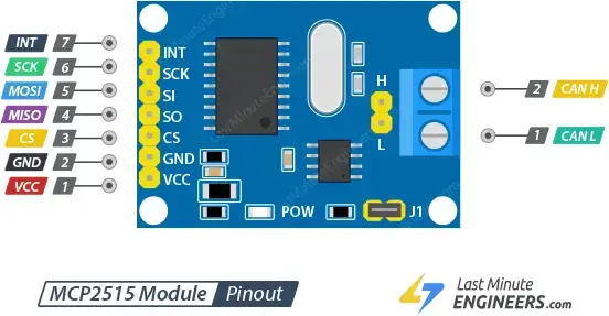
Input Connector
The breakout pins on one side of the module are used to interface with the microcontroller:
- INT: Generates an interrupt when a valid message is received and loaded into a receive buffer.
- SCK: The SPI clock pin.
- SI (MOSI): Serial data In / Master Out Slave In pin, for data sent from the Arduino to the module.
- SO (MISO): Serial data Out / Master In Slave Out pin, for data sent from the module to the Arduino.
- CS: Chip select pin, which must be held low to initiate an SPI transaction.
- GND: Common ground for power and logic.
- VCC: Power pin, which should be connected to a 5V power supply.
CAN Bus Connector
On the other side of the module, there is a 2-pin screw terminal and a 2-pin male header for connecting the CAN bus twisted pair cable:
- L: CAN low signal for the CAN Bus.
- H: CAN high signal for the CAN Bus.
Parts Required
Hardware Hookup
Now that we have a detailed understanding of the module, let’s create our own CAN network.
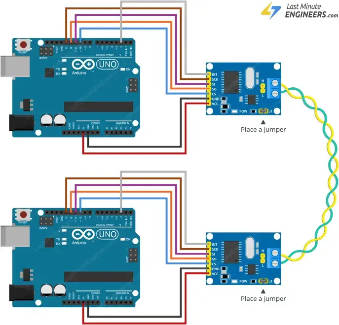
Example 1: Simple Two-Node CAN Network
In this setup, we will create a basic two-node CAN bus network where one node sends a message, and the other receives it.
Power Connections:
Connect the VCC pin on the module to 5V on the Arduino and the GND pin to ground.
SPI Connections:
Wire the SPI pins appropriately. Each Arduino board has specific SPI pin locations:
- For Arduino UNO/Nano V3.0, connect digital pin 13 to SCK, pin 12 to MISO, pin 11 to MOSI, and pin 10 to CS.
- If using a different Arduino board, refer to the official documentation for SPI pin locations.
Interrupt Pin:
Connect the module’s INT pin to digital pin 2 on the Arduino.
Construct two identical circuits, one for transmitting and one for receiving. Both circuits will have the same wiring setup.
CAN Bus Connections:
- Connect CAN L on one module to CAN L on the other.
- Connect CAN H on one module to CAN H on the other.
- While twisted pair cables are recommended for better noise immunity, simple breadboard wires can be used for short distances.
Bus Termination:
Since this is a simple two-node CAN network, place the jumper on both modules.
As bus length increases or in noisy environments, using twisted pair cables and adding shielding becomes crucial.
Construct the network as shown in your schematic or diagram.
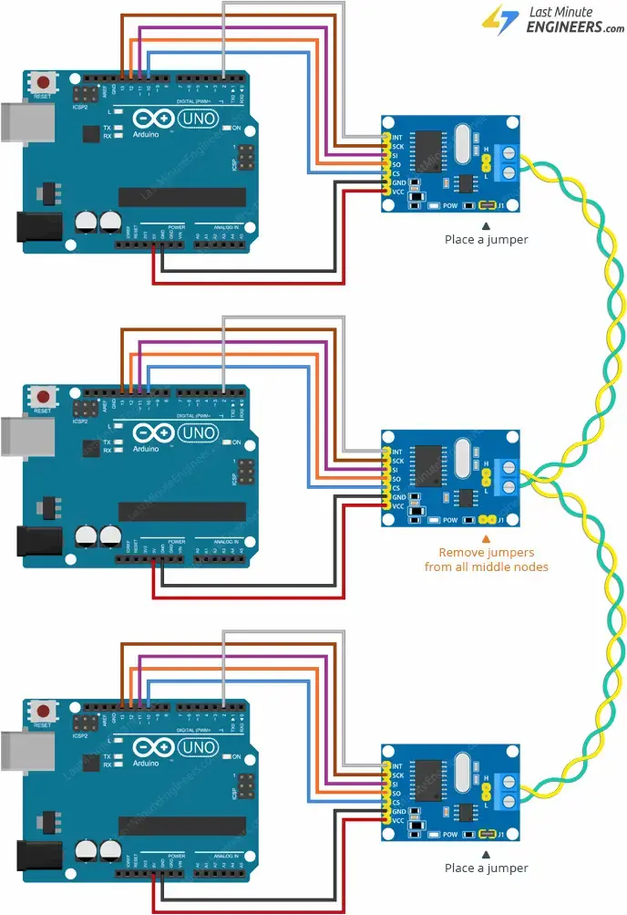
Example 2: Multi-Node CAN Network
For a larger CAN network, where multiple nodes send messages and one node relays them to a PC via a serial port:
Additional Nodes: Other nodes can be added between the two end nodes. They can be spliced in-line or attached to the main bus with a short stub cable, keeping the stub length under 12 inches.
Bus Termination: Place the jumper on the first and last nodes of the CAN network and remove it from the nodes in between.
Construct the network as shown in your schematic or diagram.
Library Installation
To work with the MCP2515 module, you need to install a suitable library in the Arduino IDE:
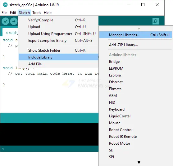
Open the Arduino IDE and navigate to Sketch > Include Library > Manage Libraries…
Wait for the Library Manager to download the library index and update the list of installed libraries.
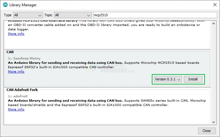
Filter the search by entering ‘mcp2515’.
Look for the CAN library by Sandeep Mistry.
Select it and click Install.
Arduino Example Code
In this simple test, we’ll send a “Hello World” message over the CAN bus and attempt to decode it. This will help you understand how to use the modules and can serve as a basis for more complex projects.
Code for the Transmitter Node
Upload the following sketch to the transmitter node. If you have multiple transmitter nodes on a CAN bus, upload this sketch to each node, but ensure each has a unique message ID.
#include <CAN.h>

void setup() {
  Serial.begin(9600);
  while (!Serial);

  Serial.println("CAN Sender");

  // start the CAN bus at 500 kbps
  if (!CAN.begin(500E3)) {
    Serial.println("Starting CAN failed!");
    while (1);
  }
}

void loop() {
  // send packet: id is 11 bits, packet can contain up to 8 bytes of data
  Serial.print("Sending packet ... ");

  CAN.beginPacket(0x12);
  CAN.write('h');
  CAN.write('e');
  CAN.write('l');
  CAN.write('l');
  CAN.write('o');
  CAN.endPacket();

  Serial.println("done");

  delay(1000);

  // send extended packet: id is 29 bits, packet can contain up to 8 bytes of data
  Serial.print("Sending extended packet ... ");

  CAN.beginExtendedPacket(0xabcdef);
  CAN.write('w');
  CAN.write('o');
  CAN.write('r');
  CAN.write('l');
  CAN.write('d');
  CAN.endPacket();

  Serial.println("done");

  delay(1000);
}
Code for the Receiver Node
Upload the following sketch to the receiver node.
#include <CAN.h>

void setup() {
  Serial.begin(9600);
  while (!Serial);

  Serial.println("CAN Receiver Callback");

  // start the CAN bus at 500 kbps
  if (!CAN.begin(500E3)) {
    Serial.println("Starting CAN failed!");
    while (1);
  }

  // register the receive callback
  CAN.onReceive(onReceive);
}

void loop() {
  // do nothing
}

void onReceive(int packetSize) {
  // received a packet
  Serial.print("Received ");

  if (CAN.packetExtended()) {
    Serial.print("extended ");
  }

  if (CAN.packetRtr()) {
    // Remote transmission request, packet contains no data
    Serial.print("RTR ");
  }

  Serial.print("packet with id 0x");
  Serial.print(CAN.packetId(), HEX);

  if (CAN.packetRtr()) {
    Serial.print(" and requested length ");
    Serial.println(CAN.packetDlc());
  } else {
    Serial.print(" and length ");
    Serial.println(packetSize);

    // only print packet data for non-RTR packets
    while (CAN.available()) {
      Serial.print((char)CAN.read());
    }
    Serial.println();
  }

  Serial.println();
}
loop function is empty for the receiver node. This sketch uses an interrupt to notify the Arduino whenever a valid message is received and loaded into one of the receive buffers.Demonstration
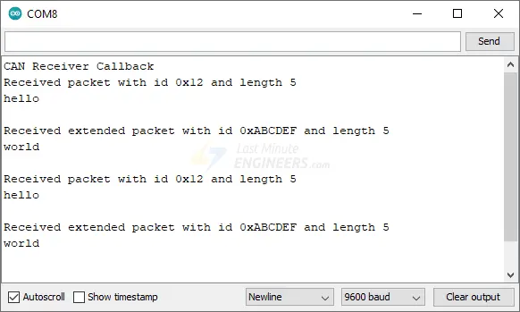
After uploading the sketch, open the serial monitor with a baud rate of 9600. The transmitter node will send a standard CAN packet and an extended CAN packet every second.
The receiver node will capture these packets and relay the data to the PC via the serial port.
- Interface a 2-Axis Joystick with Arduino: A Processing Tutorial
- Control SMS & Calls with Arduino and A6 GSM Module
- Arduino and GPS: How to Interface NEO-6M Module
- 433MHz RF Tx-Rx Modules: Arduino Interface and Operation Explained


