

During our childhood, the gyroscopes showcased at science fairs never ceased to captivate us with their peculiar movements, seemingly defying gravity. Their distinctive qualities render them indispensable in various applications, ranging from small RC helicopters to the sophisticated navigation systems aboard space shuttles.
In recent times, innovative engineers have successfully developed micromachined gyroscopes known as MEMS (microelectromechanical system) gyroscopes. These advancements have opened doors to a host of creative applications, including gesture recognition, enhanced gaming, augmented reality, panoramic photo capture, vehicle navigation, and fitness monitoring, among others.
Undoubtedly, gyroscopes and accelerometers exhibit exceptional qualities individually. However, when combined, they provide incredibly precise data about an object’s orientation. This is where the MPU6050 comes into play. The MPU6050 incorporates both a gyroscope and an accelerometer, enabling the measurement of rotation along all three axes, static acceleration due to gravity, and dynamic acceleration due to motion.
Before incorporating the MPU6050 Accelerometer into our Arduino project, it is beneficial to comprehend the workings of accelerometers and gyroscopes.
The Russian Mir space station relied on 11 gyroscopes to keep its orientation to the sun. The Hubble Space Telescope is equipped with six navigational gyros that ensure accurate pointing during observations.
Parts Required
| Component Name | Buy Now |
| Arduino Uno REV3 | Amazon |
| MPU6050 3 Axis Accelerometer Gyroscope Module 6 DOF 6-axis | Amazon |
How Does an Accelerometer Operate?
To comprehend the functioning of accelerometers, envision a ball situated within a 3D cube.
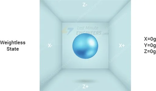
In the scenario where the cube exists in outer space, where weightlessness prevails, the ball will merely hover at the center of the cube.
Now, consider each wall representing a distinct axis.
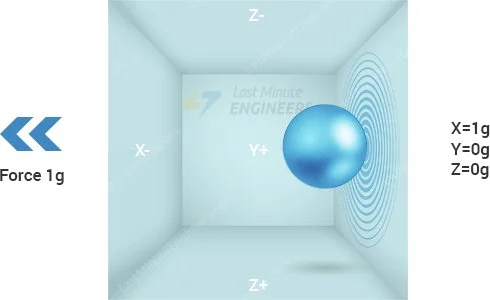
If we abruptly shift the box to the left with an acceleration of 1g (where a single G-force 1g equals gravitational acceleration of 9.8 m/s²), the ball will inevitably collide with wall X. By measuring the force exerted by the ball on wall X, we can derive an output value of 1g along the X axis.
Let’s explore the situation when we place the cube on Earth. The ball will simply fall onto wall Z, exerting a force of 1g, as depicted in the diagram below:
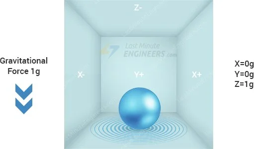
In this instance, although the box remains stationary, we still register a 1g reading on the Z axis. This is because gravity, a form of acceleration, is pulling the ball downward with a force of 1g.
While this model doesn’t precisely mirror the construction of a real-world accelerometer sensor, it proves useful in understanding why an accelerometer’s output signal is typically specified in ±g, or why an accelerometer records 1g in the z-axis when at rest, and what accelerometer readings one can anticipate in various orientations.
In reality, accelerometers utilize Micro-Electro-Mechanical Systems (MEMS fabrication technology). Let’s delve into how a MEMS accelerometer operates.
How Does a MEMS Accelerometer Function?
A MEMS (Micro-Electro-Mechanical System) accelerometer is a micro-machined structure constructed atop a silicon wafer.
This structure is suspended by polysilicon springs, enabling it to deflect when subjected to acceleration along the X, Y, and/or Z axes.
Upon deflection, the capacitance between fixed plates and those attached to the suspended structure undergoes alteration. This change in capacitance is directly proportional to the acceleration along the respective axis.
The sensor interprets this variation in capacitance and translates it into an analog output voltage.
How Does a Gyroscope Operate?
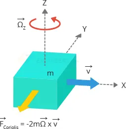
While accelerometers gauge linear acceleration, gyroscopes measure angular rotation by assessing the force generated through the Coriolis Effect.
Coriolis Effect
The Coriolis Effect posits that when a mass (m) moves in a specific direction with velocity (v), and an external angular rate (Ω) is applied (indicated by the red arrow), the resulting Coriolis Effect generates a force (depicted by the yellow arrow) that induces perpendicular motion in the mass. The degree of this displacement is directly linked to the applied angular rate.
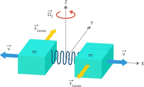
Consider two masses oscillating in opposing directions at a consistent frequency. Upon applying an angular rate, the Coriolis effect produced by each mass acts in opposite directions, leading to a proportional alteration in capacitance between the masses. The measurement of this capacitance change facilitates the calculation of the angular rate.
How Does a MEMS Gyroscope Function?
The MEMS sensor comprises a proof mass (comprising parts M1, M2, M3, and M4) perpetually oscillating to respond to the Coriolis effect. These components move inward and outward concurrently in the horizontal plane.
Upon initiating rotation of the structure, the Coriolis force acting on the moving proof mass alters the vibration from horizontal to vertical.
Three modes arise based on the axis of application for angular rotation:
Roll Mode:
With an angular rate along the X-axis, M1 and M3 move up and down out of the plane due to the Coriolis effect, causing a change in the roll angle.
Pitch Mode:
Applying an angular rate along the Y-axis leads to M2 and M4 moving up and down out of the plane, resulting in a change in the pitch angle.
Yaw Mode:
When an angular rate is applied along the Z-axis, M2 and M4 move horizontally in opposite directions, causing a change in the yaw angle.
Detection of the Coriolis effect triggers a change in capacitance (∆C), induced by the constant motion of the driving mass, which the sensing structure identifies and converts into a voltage signal.
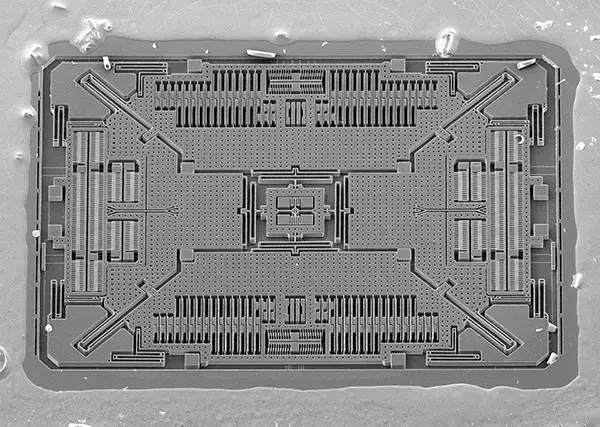
For reference, here’s an image of the MEMS structure die of a 3-axis digital gyroscope, shared by Adam McCombs.
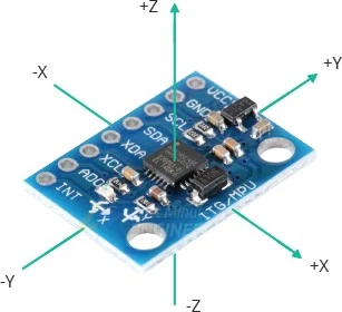
MPU6050 Module Hardware Overview
At the heart of this module lies a low-power, cost-effective 6-axis MotionTracking chip known as MPU6050. It seamlessly integrates a 3-axis gyroscope, a 3-axis accelerometer, and a Digital Motion Processor (DMP) into a compact 4mm x 4mm package.
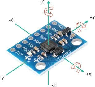
The MPU6050 Accelerometer is capable of measuring angular momentum or rotation along all three axes, static acceleration caused by gravity, and dynamic acceleration resulting from motion, shock, or vibration.
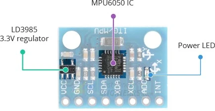
This module is equipped with an on-board LD3985 3.3V regulator, ensuring compatibility with a 5V logic microcontroller like Arduino. Notably, the MPU6050’s power consumption is minimal, drawing less than 3.6mA during measurements and a mere 5μA when idle, making it suitable for battery-powered devices.
Additionally, a Power LED on the module illuminates when the device is powered on.
Measuring Acceleration
The MPU6050 features an on-chip accelerometer capable of measuring acceleration across four programmable full-scale ranges: ±2g, ±4g, ±8g, and ±16g. Utilizing three 16-bit analog-to-digital converters, it simultaneously samples movement along the X, Y, and Z axes.
Measuring Rotation
For measuring angular rotation, the MPU6050 incorporates an on-chip gyroscope with four programmable full-scale ranges: ±250°/s, ±500°/s, ±1000°/s, and ±2000°/s. It employs three additional 16-bit analog-to-digital converters to simultaneously sample rotation along the X, Y, and Z axes, with an adjustable sampling rate ranging from 3.9 to 8000 samples per second.
Measuring Temperature
The MPU6050 Accelerometer includes an embedded temperature sensor capable of measuring temperatures from -40 to 85°C with a ±1°C accuracy. It’s important to note that this temperature measurement pertains to the silicon die itself, not the ambient temperature. Typically, these measurements are utilized for accelerometer and gyroscope calibration or to detect temperature changes rather than obtaining absolute temperatures.
The I2C Interface
Communication between the module and Arduino occurs through the I2C interface, supporting two distinct I2C addresses: 0x68HEX and 0x69HEX. This allows for the use of two MPU6050s on the same bus or prevents address conflicts with other devices. The ADO pin determines the I2C address, with an unconnected ADO pin defaulting to 0x68HEX and a connected ADO pin to 3.3V resulting in an I2C address of 0x69HEX.
Adding External Sensors
Enhancing the MPU6050 module’s accuracy is achievable by connecting external sensors. These sensors can be linked to the MPU6050 through a second, entirely independent I2C bus (XDA and XCL). Typically, this external connection is used for attaching a magnetometer, expanding the sensor’s Degrees of Freedom (DOF) from 6 to 9 (three for the accelerometer, three for the gyroscope, and three for the magnetometer).
Technical Specifications
The specifications are as follows:
| Operating Voltage | 5V (typical) |
| Accelerometer Range | ±2g, ±4g, ±8g, ±16g |
| Gyroscope Range | ±250°/s, ±500°/s, ±1000°/s, ±2000°/s |
| Temperature Range | -40 to +85°C |
| Absolute Maximum Acceleration | Up to 10,000g |
For more information, please refer to the datasheet below.
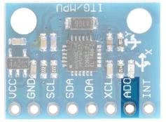
MPU6050 Accelerometer Module Pinout
The pinout for the MPU6050 module is outlined as follows:
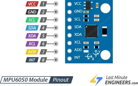
- VCC: Supplies power to the module.
- GND: Ground pin.
- SCL: Serial clock pin for the I2C interface.
- SDA: Serial data pin for the I2C interface.
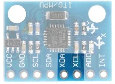
- XDA: External I2C data line. This facilitates the connection of external sensors, such as a magnetometer, via the external I2C bus.
- XCL: External I2C clock line.
- AD0: Permits the adjustment of the I2C address for the MPU6050 module. This feature helps prevent conflicts with other I2C devices or allows the connection of two MPU6050s to the same I2C bus. When the ADO pin is unconnected, the default I2C address is 0x68HEX; connecting it to 3.3V changes the I2C address to 0x69HEX.
- INT: Interrupt Output pin. The MPU6050 can be programmed to generate an interrupt upon detecting gestures, panning, zooming, scrolling, tap detection, and shake detection.
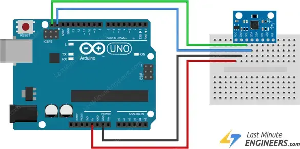
Connecting an MPU6050 Module to an Arduino
Let’s establish the connection between the MPU6050 module and the Arduino.
The wiring process is simple. Start by linking the VCC pin to the 5V output on the Arduino and the GND pin to the ground.
Next, focus on the pins designated for I2C communication. It’s important to note that different Arduino boards have distinct I2C pins that must be connected accurately. On Arduino boards featuring the R3 layout, the SDA (data line) and SCL (clock line) can be found on the pin headers near the AREF pin. They are alternatively labeled as A5 (SCL) and A4 (SDA).
Refer to the table below for a quick guide:
| MPU6050 Pin | Arduino Board R3 Pin |
|---|---|
| VCC | 5V |
| GND | GND |
| SDA | A4 |
| SCL | A5 |
This ensures a seamless connection between the MPU6050 module and the Arduino, allowing for effective I2C communication.
Library Installation
Configuring the MPU6050 Accelerometer module to initiate the capture of raw data from the device is a straightforward process. Transforming this data into meaningful information, however, presents a greater challenge. Fortunately, there are libraries available to assist in this endeavor.
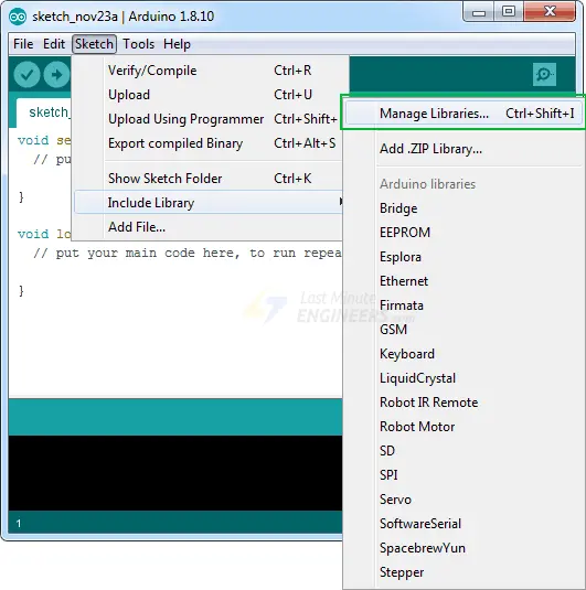
To install the library, follow these steps:
- Navigate to Sketch > Include Library > Manage Libraries…
- Wait for the Library Manager to download the library index and update the list of installed libraries.
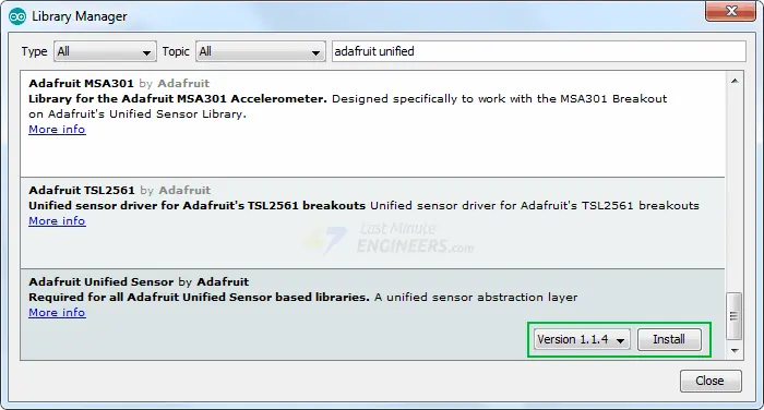
In the search bar, filter your results by entering ‘mpu6050.’ Locate the Adafruit MPU6050 Library developed by Adafruit. Click on this entry and proceed to install it.
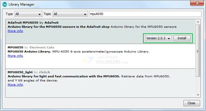
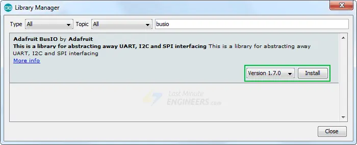
It’s crucial to note that the Adafruit MPU6050 library internally utilizes the Adafruit Unified Sensor Driver and Adafruit Bus IO Library. To ensure comprehensive functionality, search for Adafruit Unified Sensor and BusIO in the library manager and install them as well.
Arduino Example Code
Here is a simple program that reads the linear acceleration, angular rotation, and temperature from the MPU6050 module and prints them on the serial monitor.
#include <Adafruit_MPU6050.h>
#include <Adafruit_Sensor.h>
#include <Wire.h>

Adafruit_MPU6050 mpu;

void setup(void) {
	Serial.begin(115200);

	// Try to initialize!
	if (!mpu.begin()) {
		Serial.println("Failed to find MPU6050 chip");
		while (1) {
		  delay(10);
		}
	}
	Serial.println("MPU6050 Found!");

	// set accelerometer range to +-8G
	mpu.setAccelerometerRange(MPU6050_RANGE_8_G);

	// set gyro range to +- 500 deg/s
	mpu.setGyroRange(MPU6050_RANGE_500_DEG);

	// set filter bandwidth to 21 Hz
	mpu.setFilterBandwidth(MPU6050_BAND_21_HZ);

	delay(100);
}

void loop() {
	/* Get new sensor events with the readings */
	sensors_event_t a, g, temp;
	mpu.getEvent(&a, &g, &temp);

	/* Print out the values */
	Serial.print("Acceleration X: ");
	Serial.print(a.acceleration.x);
	Serial.print(", Y: ");
	Serial.print(a.acceleration.y);
	Serial.print(", Z: ");
	Serial.print(a.acceleration.z);
	Serial.println(" m/s^2");

	Serial.print("Rotation X: ");
	Serial.print(g.gyro.x);
	Serial.print(", Y: ");
	Serial.print(g.gyro.y);
	Serial.print(", Z: ");
	Serial.print(g.gyro.z);
	Serial.println(" rad/s");

	Serial.print("Temperature: ");
	Serial.print(temp.temperature);
	Serial.println(" degC");

	Serial.println("");
	delay(500);
}
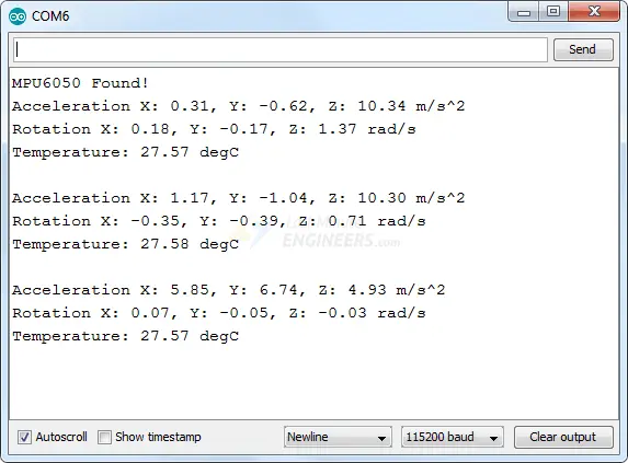
Make sure you set the baud rate to “115200” in the serial port monitor. Because the MPU6050 returns an excessive amount of data, this higher speed is required to display it.
There will be a lot of information displayed, such as linear acceleration, angular rotation, and temperature. Move your sensor around and observe how the data changes.
Code Explanation:
At the beginning of the sketch, all the necessary libraries are included. As previously stated, the Adafruit_MPU6050 library implements the hardware functions of the MPU6050 Accelerometer, while the Adafruit_Sensor library implements the unified sensor abstraction layer. Wire.h, which allows us to communicate with I2C devices, is also included.
#include <Adafruit_MPU6050.h>
#include <Adafruit_Sensor.h>
#include <Wire.h>
Next, an instance of the Adafruit_MPU6050 class is created in order to access its associated methods.
Adafruit_MPU6050 mpu;
In the setup section of the code, we first initialize the serial communication with the PC and call the begin() function. The begin() function initializes the I2C interface and verifies that the chip ID is correct. It then soft-resets the chip and waits for the sensor to calibrate after wake-up.
Serial.begin(115200);

// Try to initialize!
if (!mpu.begin()) {
	Serial.println("Failed to find MPU6050 chip");
	while (1) {
	  delay(10);
	}
}
The following three functions are then used to configure the measurement range of the MPU6050.
setAccelerometerRange(mpu6050_accel_range_t)
The setAccelerometerRange() function sets the accelerometer measurement range. This function accepts the following values:
- MPU6050_RANGE_2_G – for ±2g range (default)
- MPU6050_RANGE_4_G – for ±4g range
- MPU6050_RANGE_8_G – for ±8g range
- MPU6050_RANGE_16_G – for ±16g range
Keep in mind that the smaller the range, the more sensitive the accelerometer readings will be.
setGyroRange(mpu6050_gyro_range_t)
The setGyroRange() function sets the gyroscope measurement range. This function accepts the following values:
- MPU6050_RANGE_250_DEG – for 250 degrees-per-second range (default)
- MPU6050_RANGE_500_DEG – for 500 degrees-per-second range
- MPU6050_RANGE_1000_DEG – for 1000 degrees-per-second range
- MPU6050_RANGE_2000_DEG – for 2000 degrees-per-second range
Remember that a smaller degrees-per-second range leads to a more sensitive output.
setFilterBandwidth(mpu6050_bandwidth_t)
The setFilterBandwidth() function sets the bandwidth of the Digital Low-Pass Filter. This function accepts the following values:
- MPU6050_BAND_260_HZ – for 260 Hz bandwidth (According to the documentation, this disables the filter)
- MPU6050_BAND_184_HZ – for 184 Hz bandwidth
- MPU6050_BAND_94_HZ – for 94 Hz bandwidth
- MPU6050_BAND_44_HZ – for 44 Hz bandwidth
- MPU6050_BAND_21_HZ – for 21 Hz bandwidth
- MPU6050_BAND_10_HZ – for 10 Hz bandwidth
- MPU6050_BAND_5_HZ – for 5 Hz bandwidth
The bandwidth selection allows you to alter the low-pass filter’s cutoff frequency, allowing you to smooth out the signal by removing high-frequency noise.
In this example, we set the accelerometer range to ±8G, the gyro range to ±500°/s, and the filter bandwidth to 21 Hz.
mpu.setAccelerometerRange(MPU6050_RANGE_8_G);
mpu.setGyroRange(MPU6050_RANGE_500_DEG);
mpu.setFilterBandwidth(MPU6050_BAND_21_HZ);
In the loop section of the code, we create three objects of type sensors_event_t to hold our results. sensors_event_t is simply a user-defined datatype (structures in C) that stores a variety of sensor data such as acceleration, gyro, temperature, light, pressure, and many others. More information is available on github.
sensors_event_t a, g, temp;
The function getEvent() is then called. This function reads a new set of values from the sensor (a sensor “event”), converts them to the correct SI units and scale, and then assigns the results to our mpu object.
mpu.getEvent(&a, &g, &temp);
Finally, the values are displayed on the serial monitor.
Serial.print("Acceleration X: ");
Serial.print(a.acceleration.x);
Serial.print(", Y: ");
Serial.print(a.acceleration.y);
Serial.print(", Z: ");
Serial.print(a.acceleration.z);
Serial.println(" m/s^2");

Serial.print("Rotation X: ");
Serial.print(g.gyro.x);
Serial.print(", Y: ");
Serial.print(g.gyro.y);
Serial.print(", Z: ");
Serial.print(g.gyro.z);
Serial.println(" rad/s");

Serial.print("Temperature: ");
Serial.print(temp.temperature);
Serial.println(" degC");
Arduino Example Code – Plotting MPU6050 data
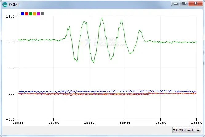
Simply looking at the raw data from the MPU6050 Accelerometer will not help. Use a Serial Plotter if you really want to see how your MPU6050 reacts when you move it around.
The Arduino IDE includes a useful tool called the serial plotter. It can provide real-time visualizations of variables. This is extremely useful for visualizing data, debugging code, and visualizing variables as waveforms.
Let’s give it a shot with the updated code below. Compile and upload the program below, then navigate to Tools > Serial Plotter (Ctrl+Shift+L). The code uses a baud rate of 115200; ensure that the serial plotter is also set to 115200.
#include <Adafruit_MPU6050.h>
#include <Adafruit_Sensor.h>
#include <Wire.h>

Adafruit_MPU6050 mpu;

void setup(void) {
	Serial.begin(115200);

	// Try to initialize!
	if (!mpu.begin()) {
		Serial.println("Failed to find MPU6050 chip");
		while (1) {
		  delay(10);
		}
	}

	// set accelerometer range to +-8G
	mpu.setAccelerometerRange(MPU6050_RANGE_8_G);

	// set gyro range to +- 500 deg/s
	mpu.setGyroRange(MPU6050_RANGE_500_DEG);

	// set filter bandwidth to 21 Hz
	mpu.setFilterBandwidth(MPU6050_BAND_21_HZ);

	delay(100);
}

void loop() {
	/* Get new sensor events with the readings */
	sensors_event_t a, g, temp;
	mpu.getEvent(&a, &g, &temp);

	/* Print out the values */
	Serial.print(a.acceleration.x);
	Serial.print(",");
	Serial.print(a.acceleration.y);
	Serial.print(",");
	Serial.print(a.acceleration.z);
	Serial.print(", ");
	Serial.print(g.gyro.x);
	Serial.print(",");
	Serial.print(g.gyro.y);
	Serial.print(",");
	Serial.print(g.gyro.z);
	Serial.println("");

	delay(10);
}
When you move the module up and down the Z axis, you should see something like this.
Code Explanation:
You’ll notice that the majority of this sketch is identical to the previous one, with the exception of:
- Temperature readings are not printed.
- All other readings are printed in such a way that they form a comma-separated list of values.
- The readings are taken every 10 milliseconds.
Related article
- Voltage Sensor Interfacing with Arduino: Step-by-Step Guide and Code
- Step-by-Step: Interfacing Multiple DS18B20 Sensors with Arduino
- Interfacing AM2320 Sensor with Arduino: Complete Tutorial
- Arduino Sound Sensor Interface: Control Devices with Clap Detection


