

Are you ready to add an auditory element to your next project?
Sound sensor Arduino are affordable, user-friendly, and capable of detecting sounds like voices, claps, or door knocks.
They open up a range of possibilities for sound-responsive projects, such as creating clap-activated lights or monitoring your pets when you’re not at home.
Inside a microphone is a thin diaphragm and a backplate. Collectively, they function as a capacitor.
When you speak into the microphone, your voice generates sound waves that strike the diaphragm, causing it to vibrate.
When the diaphragm vibrates in response to sound, the plates move closer or farther apart, causing the capacitance to change. As a result, a voltage is generated across the plates, which we can measure to determine the amplitude of the sound.
Hardware Overview
The sound sensor arduino board is compact and features a microphone (50Hz-10kHz) along with circuitry for signal conversion.
The microphone captures sound waves and converts them into an electrical signal, which is then processed by the on-board LM393 High Precision Comparator. This comparator digitizes the signal and provides it at the OUT pin.
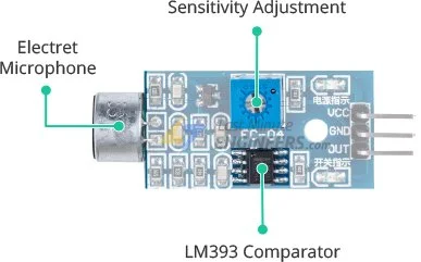
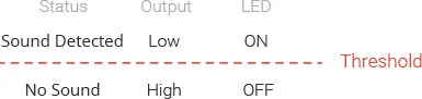
To fine-tune the sensitivity of the output signal, the module is equipped with a potentiometer. Adjusting this potentiometer allows you to set a threshold. When the sound amplitude surpasses the threshold, the module outputs a LOW signal; otherwise, it outputs a HIGH signal.
This configuration is particularly useful for triggering actions based on specific thresholds. For instance, if a knock exceeds the set threshold, you can utilize a relay to control lighting.
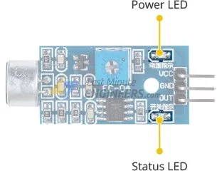
The module also incorporates two LEDs. The Power LED indicates when the module is powered on, while the Status LED illuminates when the sound level surpasses the threshold value.
Sound Sensor Pinout
The sound sensor features three pins for connectivity:
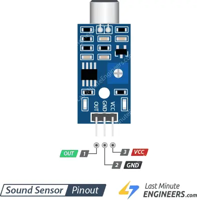
VCC: This pin is used to supply power to the sensor. It is recommended to power the sensor with a voltage ranging from 3.3V to 5V.
GND: This pin serves as the ground connection.
OUT: The OUT pin provides a HIGH signal when the surroundings are quiet and switches to LOW when sound is detected. You can connect this pin to any digital pin on an Arduino or directly to a 5V relay.
Wiring a Sound Sensor to an Arduino
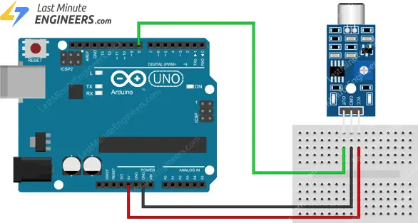
Now let’s connect the sound sensor to the Arduino.
The connections are straightforward. Begin by connecting the VCC pin of the module to the 5V pin on the Arduino, and the GND pin to the ground.
Lastly, connect the OUT pin to digital pin #8 on the Arduino. That’s all!
You can refer to the image below for the wiring diagram.
Setting the Threshold
To set the sound level threshold for the module, you can utilize the built-in potentiometer.
Follow these steps:
- Click your finger close to the microphone.
- Adjust the potentiometer while observing the module’s Status LED.
- Find the point where the LED blinks in response to your clicks.
- Once you have set the threshold, you are all set to use the module.
That’s it! Your module is now calibrated and ready for use.
Example 1 – Basic Sound Detection
The following example demonstrates how to detect claps or snaps and display a corresponding message on the serial monitor. You can try out the provided sketch, and we will discuss it in more detail later.
#define sensorPin 8

// Variable to store the time when last event happened
unsigned long lastEvent = 0;

void setup() {
	pinMode(sensorPin, INPUT);	// Set sensor pin as an INPUT
	Serial.begin(9600);
}

void loop() {
	// Read Sound sensor arduino
	int sensorData = digitalRead(sensorPin);

	// If pin goes LOW, sound is detected
	if (sensorData == LOW) {

		// If 25ms have passed since last LOW state, it means that
		// the clap is detected and not due to any spurious sounds
		if (millis() - lastEvent > 25) {
			Serial.println("Clap detected!");
		}

		// Remember when last event happened
		lastEvent = millis();
	}
}
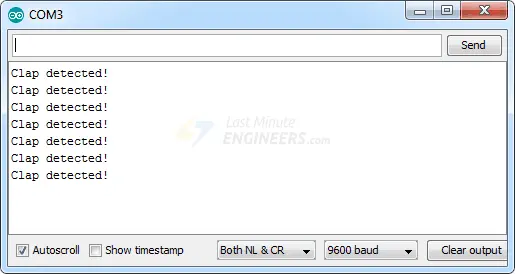
If everything is functioning correctly, the serial monitor should display the message “Clap detected!” when a clap is detected.
Code Explanation:
The provided sketch begins by declaring the Arduino pin to which the sensor’s OUT pin is connected.
#define sensorPin 8
Next, a variable named lastEvent is defined to store the time when a clap was previously detected. This variable helps prevent accidental sound detection.
unsigned long lastEvent = 0;
In the Setup section, the sensor’s OUT pin is configured as an input, and serial communication is established.
pinMode(sensorPin, INPUT);
Serial.begin(9600);
Within the loop section, the sensor output is read.
int sensorData = digitalRead(sensorPin);
When the sensor detects a sound that exceeds the threshold value, the output goes LOW. However, to avoid false triggers from background noise, a delay of 25 milliseconds is imposed after the output goes LOW. If the output remains LOW for more than 25 milliseconds, the message “Clap detected!” is printed on the serial monitor.
if (sensorData == LOW) {
	if (millis() - lastEvent > 25) {
		Serial.println("Clap detected!");
	}
	lastEvent = millis();
}
Example 2 – Controlling Devices With a Clap
In our next project, we will utilize the sound sensor to create a “Clapper” that activates AC-powered devices with a handclap.
To control AC-powered devices, we will employ a One Channel Relay Module. If you are unfamiliar with this module, we recommend referring to the provided tutorial.
Wiring
This board operates with HIGH AC voltage, and incorrect or improper usage can lead to severe injury or fatality. Therefore, it is intended for individuals who possess knowledge and familiarity with HIGH AC voltage.
The wiring for this project is straightforward.
To begin, supply power to the sound sensor and relay module. Connect their VCC pins to the Arduino’s 5V pin and GND to ground.
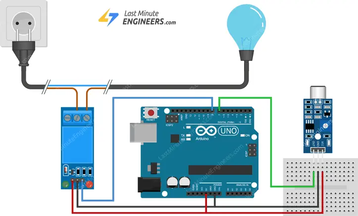
Next, establish a connection between the sound sensor’s output pin (OUT) and digital pin #7 on your Arduino. Additionally, connect the relay module’s control pin (IN) to digital pin #8.
To control the AC-powered device, you need to connect the relay module accordingly. Cut the live alternating current line and connect one end of the severed wire (from the wall) to COM and the other end to NO.
Refer to the provided diagram for the wiring configuration.
Parts Required
| Component Name | Buy Now |
| Arduino Uno REV3 | Amazon |
| 5V One Channel Relay Module | Amazon |
| Sound Microphone Sensor Detection Module | Amazon |
| Breadboard | Amazon |
Arduino Code
Below is the code for controlling devices with a clap.
#define sensorPin 7
#define relayPin 8

// Variable to store the time when last event happened
unsigned long lastEvent = 0;
boolean relayState = false;    // Variable to store the state of relay

void setup() {
	pinMode(relayPin, OUTPUT);  // Set relay pin as an OUTPUT pin
	pinMode(sensorPin, INPUT);  // Set sensor pin as an INPUT
}

void loop() {
	// Read Sound sensor
	int sensorData = digitalRead(sensorPin);

	// If pin goes LOW, sound is detected
	if (sensorData == LOW) {

	// If 25ms have passed since last LOW state, it means that
	// the clap is detected and not due to any spurious sounds
	if (millis() - lastEvent > 25) {
		//toggle relay and set the output
		relayState = !relayState;
		digitalWrite(relayPin, relayState ? HIGH : LOW);
	}

	// Remember when last event happened
	lastEvent = millis();
	}
}
Once you have uploaded the code, the device should be turned on or off each time you clap.
Code Explanation:
When comparing this sketch to the previous one, you’ll notice several similarities along with a few differences.
Initially, we declare the Arduino pin to which the relay’s control pin (IN) is connected. Additionally, we introduce a new variable called relayState to track the status of the relay.
#define relayPin 7

boolean relayState = false;
In the Setup section, we set the relayPin as an output.
pinMode(relayPin, OUTPUT);
Upon detecting the sound of a clap, instead of displaying a message on the serial monitor, we simply toggle the state of the relay.
relayState = !relayState;
digitalWrite(relayPin, relayState ? HIGH : LOW);
Troubleshooting
If you encounter issues with the Sound Sensor, follow these troubleshooting steps:
Ensure a clean power supply: The Sound Sensor is sensitive to power supply noise, so make sure the power source is free from any interference or fluctuations.
Minimize mechanical vibration and wind noise: The sensor is sensitive to vibrations and wind noise. Mounting the sensor on a stable surface can help reduce these disturbances.
Consider the sensing range: Keep in mind that this sound sensor arduino has a limited sensing range, typically around 10 inches. For accurate readings, generate the noise closer to the sensor to ensure reliable detection.
Related article
- Arduino Soil NPK Sensor: Maximizing Plant Nutrition
- Soil Moisture Sensor: How It Works and Arduino Interface Guide
- How to Interface Capacitive Soil Moisture Sensor with Arduino
- Interface Rain Sensor with Arduino: Step-by-Step Tutorial
- Interface Water Level Sensor with Arduino: Step-by-Step Tutorial


