
Many individuals are operating drones nowadays, and having knowledge of the altitude your drone attains is valuable. Bosch’s BMP388, boasting remarkable speed, temperature stability, and pinpoint accuracy as a barometric pressure sensor, could serve as an ideal option for altitude tracking in your upcoming drone project.
Parts Required
Hardware Overview
At the core of this module lies Bosch’s next-generation digital pressure and temperature sensor, the Arduino BMP388.
The BMP388 Pressure Sensor
The BMP388 is distinguished as an exceptionally compact, impressively fast, accurate, energy-efficient, and noise-reducing absolute barometric pressure sensor. It enables precise altitude tracking, rendering it ideal for drone applications or any project necessitating monitoring of altitude above sea level.

With the capability to measure barometric pressure from 300 hPa to 1250 hPa, the Arduino BMP388 boasts a relative accuracy of 8 Pascals, approximately equivalent to ±0.5 meters of altitude.
Featuring an integrated on-chip temperature sensor, the BMP388 enables compensation for environmental variations and calibration of measurements. This temperature sensor delivers reasonably precise readings of the ‘die temperature’ ranging from -40°C to +85°C, with an accuracy of ±1°C.
Power Requirement
The module is furnished with a MIC5219 3.3V precise voltage regulator and voltage level translator, ensuring seamless compatibility with your preferred 3.3V or 5V microcontroller.
Operating at less than 0.7mA during measurements and a mere 2µA during sleep mode, the BMP388 boasts remarkably low power consumption, making it well-suited for integration into battery-powered devices like handsets, wearables, or smartwatches.
Digital interfaces
The sensor offers communication options through either I2C or SPI.
I2C Interface
For communication with the Arduino, the sensor utilizes the I2C interface. It provides support for two distinct I2C addresses: 0x77Hex and 0x76Hex. This setup enables the use of two Arduino BMP388 modules on the same bus or helps prevent address conflicts with other devices on the bus.
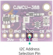
The SDO pin determines the I2C address of the module and comes with a built-in pull-up resistor. Leaving the SDO pin unconnected defaults the I2C address to 0x77Hex, while connecting it to GND pulls the line LOW, setting the I2C address to 0x76Hex.
SPI Interface
Additionally, the sensor can communicate via the SPI interface.
Modes of Operation
The BMP388 offers three modes of operation:
- SLEEP_MODE: This mode places the device into an inactive standby state, where no measurements are carried out.
- NORMAL_MODE: In this mode, the BMP388 conducts continuous conversions with intervals determined by the standby time.
- FORCED_MODE: Operating in this mode initiates a single conversion, after which the device returns to SLEEP_MODE.
FIFO Buffer
Integrated within the BMP388 is a FIFO (first-in-first-out) buffer with a capacity of 512 bytes. This buffer can store up to 72 pressure and/or temperature measurement results. By utilizing the FIFO buffer, the microcontroller is relieved from the task of reading each new data sample from the sensor, leading to power savings within the system.
Interrupts
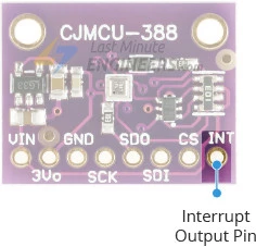
The BMP388 features an interrupt (INT) output pin, enabling measurement-driven interrupts instead of polling, allowing the host microcontroller to handle other tasks while the sensor collects data. The interrupt can be activated for three different sources:
- Data Ready: This triggers after a pressure and temperature measurement concludes, storing conversion results in the data registers and FIFO.
- FIFO Watermark: This triggers when the fill level of the FIFO reaches a pre-set limit.
- FIFO Full: This triggers when the FIFO reaches capacity, signaling potential loss of future data.
The INT pin output drive can be set as PUSH_PULL or OPEN_COLLECTOR, and the INT pin level can be configured as ACTIVE_LOW or ACTIVE_HIGH. The interrupt itself can operate in UNLATCHED or LATCHED mode. In UNLATCHED mode, the interrupt signal automatically clears after 2.5ms, whereas in LATCHED mode, the interrupt signal remains active until the data is read.
Technical Specifications
Here are the complete specifications:
| Power supply | 3.3V to 5.5V |
| Current draw | ~0.7mA (during measurements) |
| ~2µA (during standby mode) | |
| Pressure Measurement Range | 300Pa to 1250 hPa |
| Pressure Absolute Accuracy | ±0.5 hPa |
| Temperature Range | -40˚C to +85˚C |
| Temperature Accuracy | ±1˚C |
For more details, please refer below datasheet.
BMP388 Module Pinout
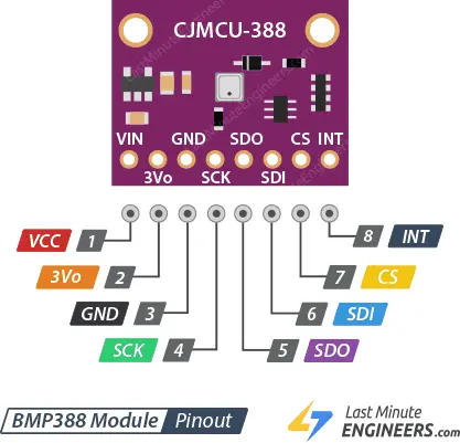
Let’s examine the pin configuration in detail:
Power Pins:
- VCC: This serves as the power pin and can be linked to the 5V output of your Arduino.
- 3Vo: This pin provides a 3.3V output from the voltage regulator. If necessary, you can draw up to 100mA from this pin.
- GND: This pin acts as the common ground for both power and logic.
SPI Logic pins:
- SCK: This is the SPI Clock pin, functioning as an input to the chip.
- SDO: The Serial Data Out (MISO) pin is used for transmitting data from the BMP388 to your microcontroller.
- SDI: The Serial Data In (MOSI) pin is employed for sending data from your microcontroller to the BMP388.
- CS: This is the Chip Select pin. Lowering it to LOW enables SPI communication. If you plan to connect multiple Arduino BMP388 modules to a single microcontroller, they can share the SDI, SDO, and SCK pins, with each having its unique CS pin assignment.
I2C Logic pins:
- SCK: This serves as the I2C clock pin, to be connected to your microcontroller’s I2C clock line.
- SDI: Also functioning as the I2C data pin, it should be connected to your microcontroller’s I2C data line.
- SDO: This pin determines the I2C address of the module. If left unconnected, the default I2C address is 0x77Hex. When connected to GND, the line is pulled LOW, setting the I2C address to 0x76Hex.
Interrupt Pin:
- INT: This is the Interrupt pin. The BMP388 can be programmed to generate interrupts for specific events. Please refer to the Interrupts section for more details.
Connecting a BMP388 Module to an Arduino
Now that we have a comprehensive understanding of the module, let’s proceed to connect it to our Arduino!
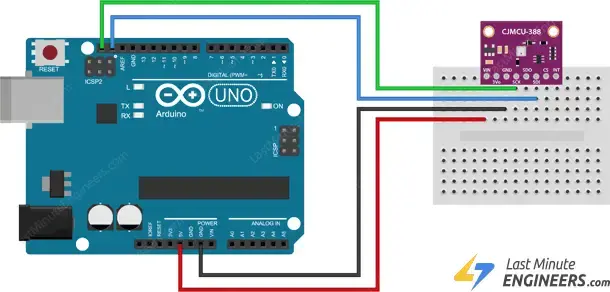
I2C Wiring
If you prefer to use the I2C interface, follow these wiring instructions:
Begin by linking the VCC pin to the power supply, ensuring it falls within the 3V-5V range. Match the voltage to that of your microcontroller’s logic. Typically, for most Arduinos, this is 5V. If you’re using 3.3V logic devices, opt for 3.3V. Then, connect GND to the common ground.
Connect the SCK pin to the I2C clock pin and the SDI pin to the I2C data pin on your Arduino. Remember that each Arduino board features distinct I2C pins, which must be connected accordingly. For Arduino boards with the R3 layout, the SDA (data line) and SCL (clock line) are located on the pin headers close to the AREF pin, often labeled as A5 (SCL) and A4 (SDA).
The following diagram depicts the wiring setup.
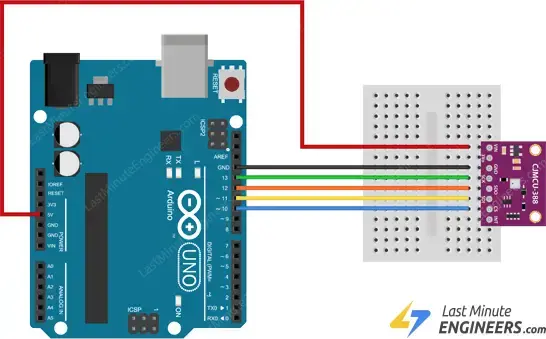
SPI Wiring
As the sensor supports SPI, you have the option to utilize either hardware or software SPI. However, it’s advisable to employ hardware SPI pins, as they offer significantly faster performance compared to implementing the interface code through ‘bit-banging’ using another set of pins.
Once again, it’s crucial to note that each Arduino board features distinct SPI pins, which should be connected accordingly. For Arduino boards like the UNO/Nano V3.0, these pins are digital 13 (SCK), 12 (MISO), 11 (MOSI), and 10 (SS).
If you’re using a different Arduino board, it’s recommended to consult the official documentation regarding SPI pin locations before proceeding.
The following diagram illustrates the wiring.
Once you’ve established the connection between your module and the Arduino, it’s time to start coding!
Installing the Library
To commence reading sensor data, you’ll need to install the Adafruit BMP3XX library. This library can be obtained from the Arduino library manager.
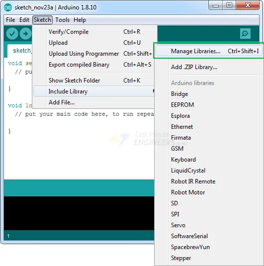
Here’s how to install the library:
Navigate to Sketch > Include Library > Manage Libraries…
Allow the Library Manager to download the libraries index and update the list of installed libraries.
Filter your search by typing ‘adafruit bmp3xx’ and proceed to install the library.
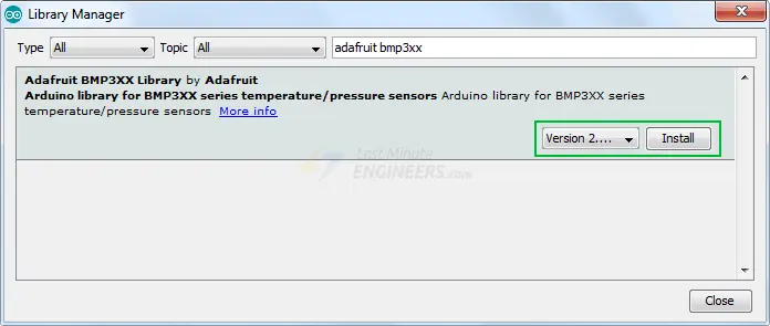
Additionally, the BMP3XX sensor library relies on the Adafruit Sensor support backend. Therefore, search for the Adafruit Unified Sensor in the library manager and install it as well (you may need to scroll down a bit to find it).

Arduino Code – Reading Pressure, Altitude and Temperature
Below is a simple Arduino sketch. Upload it to your Arduino board, and you should observe pressure, temperature, and approximate altitude readings on the serial monitor.
#include <Wire.h>
#include <SPI.h>
#include <Adafruit_Sensor.h>
#include "Adafruit_BMP3XX.h"

//Uncomment if you want to use SPI
//#define BMP_SCK 13
//#define BMP_MISO 12
//#define BMP_MOSI 11
//#define BMP_CS 10

#define SEALEVELPRESSURE_HPA (1013.25)

Adafruit_BMP3XX bmp;

void setup() {
  Serial.begin(115200);
  while (!Serial);

  if (!bmp.begin_I2C()) {   // hardware I2C mode, can pass in address & alt Wire
  //if (! bmp.begin_SPI(BMP_CS)) {  // hardware SPI mode
  //if (! bmp.begin_SPI(BMP_CS, BMP_SCK, BMP_MISO, BMP_MOSI)) {  // software SPI mode
    Serial.println("Could not find a valid BMP3 sensor, check wiring!");
    while (1);
  }

  // Set up oversampling and filter initialization
  bmp.setTemperatureOversampling(BMP3_OVERSAMPLING_8X);
  bmp.setPressureOversampling(BMP3_OVERSAMPLING_4X);
  bmp.setIIRFilterCoeff(BMP3_IIR_FILTER_COEFF_3);
  bmp.setOutputDataRate(BMP3_ODR_50_HZ);
}

void loop() {
  if (! bmp.performReading()) {
    Serial.println("Failed to perform reading :(");
    return;
  }
  Serial.print("Temperature = ");
  Serial.print(bmp.temperature);
  Serial.println(" *C");

  Serial.print("Pressure = ");
  Serial.print(bmp.pressure / 100.0);
  Serial.println(" hPa");

  Serial.print("Approx. Altitude = ");
  Serial.print(bmp.readAltitude(SEALEVELPRESSURE_HPA));
  Serial.println(" m");

  Serial.println();
  delay(2000);
}
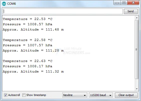
Note that you must set your serial monitor to a speed of 115200 baud to try out the sketch.
You’ll observe various data displaying pressure, temperature, and approximate altitude values. Experiment by moving your sensor around and observe how the data changes.
Code Explanation:
The sketch begins by including four essential libraries: Wire.h (for I2C), SPI.h (for SPI), Adafruit_Sensor.h, and Adafruit_BMP3XX.h.
#include <Wire.h>
#include <SPI.h>
#include <Adafruit_Sensor.h>
#include "Adafruit_BMP3XX.h"
This sketch utilizes the I2C communication protocol to interact with the sensor. However, it is prepared to support SPI as well. To switch to SPI, you simply need to uncomment the following lines of code defining the SPI pins.
//#define BMP_SCK 13
//#define BMP_MISO 12
//#define BMP_MOSI 11
//#define BMP_CS 10
Next, a variable named SEALEVELPRESSURE_HPA is defined. This variable stores the sea level pressure in millibars and is utilized to estimate altitude based on a given pressure by comparing it with the sea level pressure. This sketch employs the default value, but for precise results, replace it with the current sea level pressure at your location.
#define SEALEVELPRESSURE_HPA (1013.25)
The subsequent line creates an Adafruit_BMP3XX object named bmp.
Adafruit_BMP3XX bmp;
In the setup section, we initialize serial communication with the PC and call the begin() function.
The bmp.begin_I2C() function initializes the I2C interface and verifies if the chip ID is correct. It then performs a soft reset on the chip and waits for calibration after wake-up. Similarly, the bmp.begin_SPI() function initializes the SPI interface. If you intend to use SPI, you must uncomment the corresponding if statement.
Serial.begin(115200);
while (!Serial);
Serial.println("Adafruit BMP388 / BMP390 test");

if (!bmp.begin_I2C()) {   // hardware I2C mode, can pass in address & alt Wire
	//if (! bmp.begin_SPI(BMP_CS)) {  // hardware SPI mode
	//if (! bmp.begin_SPI(BMP_CS, BMP_SCK, BMP_MISO, BMP_MOSI)) {  // software SPI mode
	Serial.println("Could not find a valid BMP3 sensor, check wiring!");
	while (1);
}
Subsequently, we configure some parameters for the sensor.
bmp.setTemperatureOversampling(BMP3_OVERSAMPLING_8X);
bmp.setPressureOversampling(BMP3_OVERSAMPLING_4X);
bmp.setIIRFilterCoeff(BMP3_IIR_FILTER_COEFF_3);
bmp.setOutputDataRate(BMP3_ODR_50_HZ);
Let’s delve into each function one by one.
setTemperatureOversampling(uint8_t os)
This function adjusts the oversampling level for temperature measurements in order to enhance effective resolution and diminish noise. It accepts one of the following parameters:
- BMP3_NO_OVERSAMPLING (disables oversampling)
- BMP3_OVERSAMPLING_2X
- BMP3_OVERSAMPLING_4X
- BMP3_OVERSAMPLING_8X
- BMP3_OVERSAMPLING_16X
- BMP3_OVERSAMPLING_32X
setPressureOversampling(uint8_t os)
setPressureOversampling(uint8_t os)
Similar to the temperature oversampling function, this function modifies the oversampling level for pressure measurements. It also supports the same set of parameters.
setIIRFilterCoeff(uint8_t fs)
The Arduino BMP388 incorporates an internal IIR filter to mitigate short-term pressure variations in sensor output caused by external disturbances. This function sets the size of the IIR filter, allowing for filtering coefficients to be adjusted. The available parameters are:
- BMP3_IIR_FILTER_DISABLE (disables filtering)
- BMP3_IIR_FILTER_COEFF_1
- BMP3_IIR_FILTER_COEFF_3
- BMP3_IIR_FILTER_COEFF_7
- BMP3_IIR_FILTER_COEFF_15
- BMP3_IIR_FILTER_COEFF_31
- BMP3_IIR_FILTER_COEFF_63
- BMP3_IIR_FILTER_COEFF_127
It’s important to note that higher IIR filter coefficients deliver more stable measurements but may result in slower response times.
setOutputDataRate(uint8_t odr)
The function setOutputDataRate() adjusts the output data rate, which represents the maximum frequency at which you can retrieve data from the device based on the specified settings. It accepts one of the following parameters:
- BMP3_ODR_200_HZ
- BMP3_ODR_100_HZ
- BMP3_ODR_50_HZ
- BMP3_ODR_25_HZ
- BMP3_ODR_12_5_HZ
- BMP3_ODR_6_25_HZ
- BMP3_ODR_3_1_HZ
- BMP3_ODR_1_5_HZ
- BMP3_ODR_0_78_HZ
- BMP3_ODR_0_39_HZ
- BMP3_ODR_0_2_HZ
- BMP3_ODR_0_1_HZ
- BMP3_ODR_0_05_HZ
- BMP3_ODR_0_02_HZ
- BMP3_ODR_0_01_HZ
- BMP3_ODR_0_006_HZ
- BMP3_ODR_0_003_HZ
- BMP3_ODR_0_001_HZ
In the loop, we invoke the bmp.performReading() function to execute a reading. Subsequently, we can access the instance variables of the object (bmp) using the dot operator.
- bmp.temperature: Returns the temperature reading.
- bmp.pressure: Returns the barometric pressure reading.
- bmp.readAltitude(SEALEVELPRESSURE_HPA): This function calculates the altitude (in meters) based on the specified atmospheric pressure (in hPa) and sea-level pressure (in hPa).
void loop() {
  if (! bmp.performReading()) {
    Serial.println("Failed to perform reading :(");
    return;
  }
  Serial.print("Temperature = ");
  Serial.print(bmp.temperature);
  Serial.println(" *C");

  Serial.print("Pressure = ");
  Serial.print(bmp.pressure / 100.0);
  Serial.println(" hPa");

  Serial.print("Approx. Altitude = ");
  Serial.print(bmp.readAltitude(SEALEVELPRESSURE_HPA));
  Serial.println(" m");

  Serial.println();
  delay(2000);
}
Related article
- Track Heart Rate: A Guide to Pulse Sensor and Arduino Integration
- Using TMP36 Temperature Sensor: Arduino Interfacing Guide
- Arduino Water Quality Testing: Utilizing the TDS Sensor
- Interfacing Arduino with TCS230/TCS3200 Color Recognition Sensor


