
Looking to monitor the climate in your greenhouse, create a humidor control system, or gather temperature and humidity data for a weather station project? The AOSONG DHT11 Temperature and Humidity sensor module might be just what you need!
This sensor comes pre-calibrated from the factory and doesn’t need any additional components to operate. With simple connections and a little bit of Arduino code, you’ll be able to start measuring relative humidity and temperature in no time.
Parts Required
| Component Name | Buy Now |
| Arduino Uno REV3 | Amazon |
| DHT11 Temperature Humidity Sensor Module | Amazon |
| I2C 1602 LCD Display Module | Amazon |
| Breadboard | Amazon |
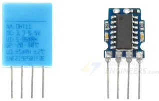
DHT11 Module: Overview of Hardware Components
The DHT11 module features the AOSONG DHT11 digital temperature and humidity sensor at its core.
DHT11 Sensor
The DHT11 sensor can accurately measure temperatures ranging from 0°C to 50°C with a precision of ±2.0°C. It can also measure humidity levels from 20% to 80% with a 5% accuracy.
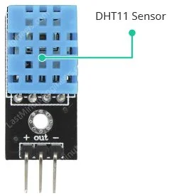
It’s important to note that the DHT11 has a sampling rate of 1Hz, which means it provides new data once per second.
Supporting Circuitry
The module is equipped with all the necessary supporting circuitry, allowing for immediate use.
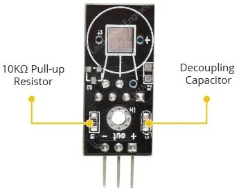
Typically, DHT11 sensors require an external 10K pull-up resistor on the output pin to ensure proper communication with the Arduino. However, the module already includes a built-in pull-up resistor, eliminating the need for an additional one.
Additionally, the module incorporates a decoupling capacitor to filter out power supply noise for reliable operation.
Inside the DHT11 Sensor: Component Overview
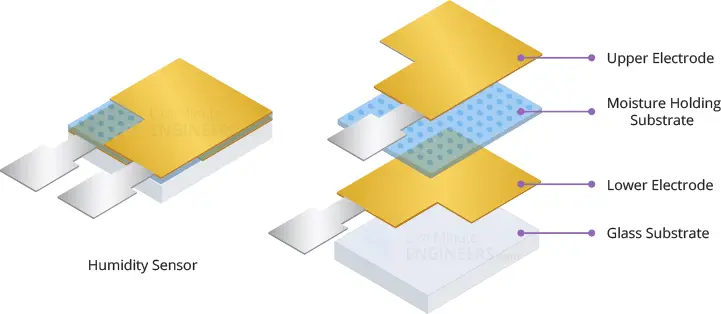
Upon removing the casing of the DHT11 sensor, you will find two key components: an NTC thermistor and a humidity sensing component.
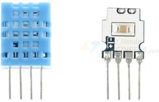
The humidity sensing component consists of two electrodes separated by a moisture-holding substrate, typically composed of a salt or conductive plastic polymer.
As the humidity level increases, the substrate absorbs water vapor, resulting in the release of ions and a decrease in resistance between the electrodes.
This change in resistance is directly proportional to the humidity level, allowing for the estimation of relative humidity.
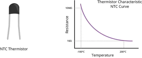
The DHT11 sensor also incorporates an NTC thermistor for temperature measurement. A thermistor is a type of resistor that exhibits varying resistance in response to temperature changes.
While all resistors technically exhibit some change in resistance with temperature, the variation is usually minimal and challenging to measure accurately. Thermistors, on the other hand, are specifically designed to exhibit significant resistance changes with temperature, often by 100 ohms or more per degree. The “NTC” designation refers to “Negative Temperature Coefficient,” indicating that the resistance decreases as the temperature rises.
Additionally, the sensor includes an 8-bit SOIC-14 packaged IC. This integrated circuit plays a crucial role in the sensor’s functionality. It measures and processes the analog signal, utilizing stored calibration coefficients. It then converts the analog signal to digital form and generates a digital output signal containing the temperature and humidity values.
DHT11 Module Pinout
Connecting the DHT11 module is a straightforward process. It features only three pins:
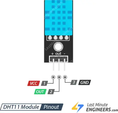
VCC (+) Pin: This pin supplies power to the sensor. Although the module’s supply voltage can range from 3.3V to 5.5V, it is recommended to use a 5V power supply. With a 5V power source, the sensor can be positioned up to 20 meters away. However, when using a 3.3V supply voltage, the sensor’s range is limited to just 1 meter to avoid measurement errors caused by line voltage drop.
Out Pin: The Out pin serves as the communication link between the sensor and the microcontroller.
GND (-) Pin: This pin is the ground connection for the module.
Connecting the DHT11 Module to Arduino
Let’s proceed with connecting the DHT11 module to your Arduino!
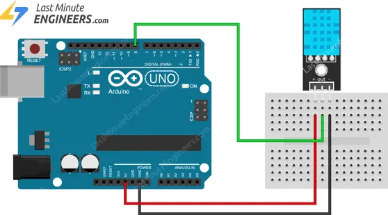
The wiring is quite straightforward. Start by connecting the + (VCC) pin of the DHT11 module to the 5V output of your Arduino board. Next, connect the – (GND) pin to the ground (GND) pin on the Arduino. Finally, establish a connection between the Out pin of the module and digital pin #8 on the Arduino.
Refer to the diagram below for a visual representation of the wiring setup.
DHT Library Installation
The DHT sensors utilize their own specialized single-wire data transfer protocol, which relies on precise timing. However, we can simplify this process by using the DHTlib library, which takes care of most of the complexities.
To install the library, follow these steps:
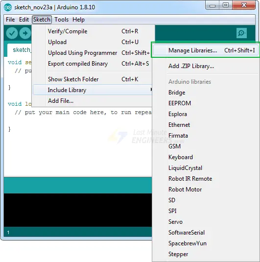
Open the Arduino IDE and go to Sketch > Include Library > Manage Libraries…
Wait for the Library Manager to download the libraries index and update the list of installed libraries.
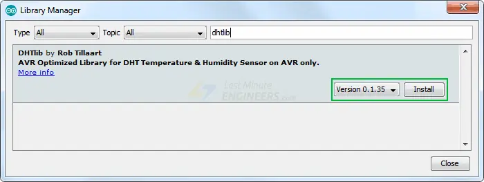
In the search field, enter ‘dhtlib’ to filter the results.
You should see a single entry for the DHT library. Finally, click on the Install button to install the DHT library.
Once the installation is complete, you’re ready to start using the DHTlib library for your projects.
Arduino Example 1 – Displaying Readings on Serial Monitor
Once you have installed the library, simply copy and paste this sketch into the Arduino IDE.
The provided test sketch will display the temperature and relative humidity values on the serial monitor. Give the sketch a try, and then we can examine it more closely.
#include <dht.h>        // Include library
#define outPin 8        // Defines pin number to which the sensor is connected

dht DHT;                // Creates a DHT object

void setup() {
	Serial.begin(9600);
}

void loop() {
	int readData = DHT.read11(outPin);

	float t = DHT.temperature;        // Read temperature
	float h = DHT.humidity;           // Read humidity

	Serial.print("Temperature = ");
	Serial.print(t);
	Serial.print("°C | ");
	Serial.print((t*9.0)/5.0+32.0);        // Convert celsius to fahrenheit
	Serial.println("°F ");
	Serial.print("Humidity = ");
	Serial.print(h);
	Serial.println("% ");
	Serial.println("");

	delay(2000); // wait two seconds
}
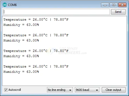
After uploading the sketch, you should see the following output on the serial monitor.
Code Explanation:
The provided sketch begins by including the DHT library. Then, we define the Arduino pin number to which the Data pin of our sensor is connected, and create a DHT object.
#include <dht.h>
#define outPin 8

dht DHT;
In the setup function, we initialize the serial communication.
void setup() {
  Serial.begin(9600);
}
Inside the loop function, we use the read11() function to read data from the DHT11 module. This function requires the Data pin number of the sensor as a parameter.
int readData = DHT.read11(outPin);
After reading the data, we can retrieve the temperature and humidity values by accessing the corresponding properties of the DHT object using dot notation.
float t = DHT.temperature;    // Read temperature
float h = DHT.humidity;       // Read humidity
The temperature value returned by the DHT object is in degrees Celsius (°C). If you want to convert it to Fahrenheit (°F), you can use the following formula:
T(°F) = T(°C) × 9/5 + 32
To print the temperature in Fahrenheit, the sketch uses the Serial.print() function with the calculated value.
Serial.print((t * 9.0) / 5.0 + 32.0);
Arduino Example 2 – Displaying Readings on LCD
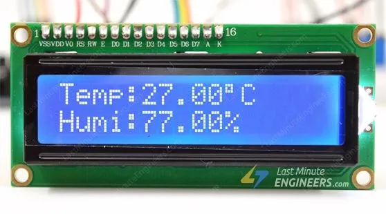
If you’re working on a project such as building an incubator and you need to display the current temperature and humidity levels, using a 16×2 character LCD is a better option than the serial monitor. In this example, we will connect the LCD to the Arduino along with the DHT11 module.
Here is an example of what the output will look like.
If you are not familiar with 16×2 character LCDs, we recommend reading the tutorial provided below.
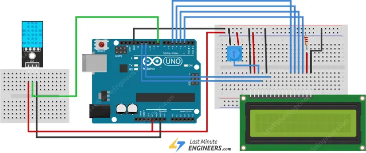
Wiring
Next, connect the LCD according to the following diagram.
Arduino Code
The code below will display the temperature and relative humidity values on the 16×2 character LCD. This sketch is similar to the previous one, with the difference that the values are printed on the LCD.
#include <LiquidCrystal.h>      // Include LiquidCrystal Library
#include <dht.h>

#define outPin 8

LiquidCrystal lcd(12, 11, 5, 4, 3, 2); // Create an LCD object.
dht DHT;                // Create a DHT object

void setup() {
	lcd.begin(16,2); 	// Initialize the LCD
}

void loop() {
	int readData = DHT.read11(outPin);

	float t = DHT.temperature;
	float h = DHT.humidity;

	lcd.setCursor(0,0);
	lcd.print("Temp.: ");
	lcd.print(t);
	lcd.print((char)223);	//shows degrees character
	lcd.print("C");

	lcd.setCursor(0,1);
	lcd.print("Humi.: ");
	lcd.print(h);
	lcd.print("%");

	delay(2000);
}
Related article
- Understanding the Operation of HC-SR04 Ultrasonic Sensor and Connecting it to Arduino
- Arduino Soil NPK Sensor: Maximizing Plant Nutrition
- Step-by-Step: Connecting Reed Switch to Arduino
- Track Heart Rate: A Guide to Pulse Sensor and Arduino Integration
- Using TMP36 Temperature Sensor: Arduino Interfacing Guide


