

Undoubtedly, the L293D and L298N are popular motor drivers widely used in Arduino projects. They have earned a reputation for their reliability and have been utilized in countless projects. However, they do come with a significant drawback – their use of bipolar junction transistors (BJTs) makes them highly inefficient.
The issue with BJTs lies in their on-state voltage drop, which results in energy loss that dissipates as heat. Over time, this can lead to considerable energy wastage and even cause the driver to overheat, especially in projects that need to operate for extended durations.
Fortunately, modern motor drivers, such as the DRV8833 arduino, excel in efficiency. Instead of relying on BJTs, the DRV8833 employs MOSFETs. These MOSFETs have an almost negligible voltage drop, meaning that nearly all the power supply voltage is effectively delivered to the motor. Consequently, the DRV8833 not only proves to be more energy-efficient compared to BJT-based motor drivers but also generates significantly less heat, making it safer for prolonged usage.
Now, let’s delve into the impressive capabilities of the DRV8833 motor driver and explore its remarkable features.
DRV8833 Motor Driver
The DRV8833 Motor Driver is a compact and efficient integrated H-Bridge driver IC manufactured by Texas Instruments. It is specifically designed for motor driving applications, offering a versatile solution for controlling various types of motors, including two DC brush motors, a bipolar stepper motor, solenoids, and other inductive loads.

The DRV8833 operates within a voltage range of 2.7V to 10.8V, making it suitable for low-voltage applications. It can continuously supply up to 1.2A per channel, and for short bursts, it can handle peak currents of up to 2A per channel.
To ensure reliable and safe operation, the DRV8833 includes several protective features, such as under-voltage lockout, over-current protection, and over-temperature protection. If any of these events occur, the H-Bridge MOSFETs are disabled, preventing damage to the driver and connected motors. Once the fault condition is resolved, the driver automatically resumes normal operation.
Additionally, the DRV8833 features a low-power sleep mode, which enables power-saving functionality when the motors are not actively in use, making it an energy-efficient choice for battery-powered applications.
Overall, the DRV8833 Motor Driver’s compact size, efficiency, and protective features make it an excellent choice for a wide range of motor control applications in various electronic projects.
Technical Specifications
Here are the specifications:
| Motor Voltage | 2.7V – 10.8V |
| Logic Voltage | 3V- and 5V-compatible |
| Continuous Output Current | 1.2A (Per Channel) |
| Peak Output Current | 2A (Per Channel) |
| Motor Channels | 2 |
| Protection Features | under-voltage lockout, over-current, and over-temperature |
For more information, please refer to the datasheet below.
DRV8833 Motor Driver Pinout
The DRV8833 driver has a total of 12 pins that connect it to the outside world. The pinout is as follows:
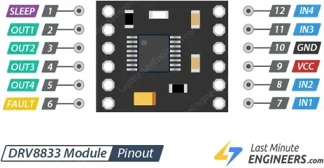
Let’s get to know all the pins one by one.
Power Pins
The DRV8833 motor driver module has two power pins:
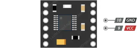
VCC: This pin is used to connect the positive terminal of the power supply that drives the motors. The voltage supplied to this pin can range from 2.7V to 10.8V. The DRV8833 arduino can operate efficiently even with low voltages as low as 2.7V, making it suitable for low-voltage projects, such as those powered by single-cell LiPo batteries and low-voltage motors.
GND: This pin is used to connect the ground of the power supply, completing the circuit. It is essential to provide a common ground reference between the motor driver and the connected components for proper functioning.
Unlike some motor drivers that have separate power supply connections for the logic and motor voltage, the DRV8833 uses a single power supply connection since the motor voltage matches the logic voltage. This design simplifies the wiring and power management for the motor driver.
Output Pins
The DRV8833 motor driver module has four output pins, namely OUT1, OUT2, OUT3, and OUT4. These output pins are used to connect the motors to the driver and control their operation. Here’s how they are utilized:

OUT1 and OUT2: These output pins are used to control Motor A. You connect the positive and negative terminals of Motor A to OUT1 and OUT2, respectively. By applying different logic levels (HIGH or LOW) to the control input pins IN1 and IN2, you can control the speed and spinning direction of Motor A. The truth table provided in the driver’s documentation explains how these inputs affect the motor’s behavior.
OUT3 and OUT4: These output pins are used to control Motor B. Similar to Motor A, you connect the positive and negative terminals of Motor B to OUT3 and OUT4, respectively. By applying appropriate logic levels to the control input pins IN3 and IN4, you can control the speed and spinning direction of Motor B.
The DRV8833 motor driver can handle voltages from 2.7V to 10.8V and can supply a continuous current of up to 1.2A per channel, with peak currents up to 2A for a few seconds. This makes it suitable for driving small DC brushed motors within this voltage and current range. By using the appropriate control signals on the output pins, you can precisely control the movements and direction of the connected motors in your Arduino projects.
Control Input Pins
The DRV8833 motor driver has control input pins that are used to determine the speed and spinning direction of the connected motors. These control input pins are divided into two sets, each set responsible for controlling a separate motor (Motor A and Motor B). Here’s a detailed explanation of the control input pins:
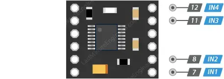
For Motor A:
IN1: This input pin controls the spinning direction of Motor A. To make Motor A spin forward, you apply a logic HIGH (5V) signal to this pin. For reverse spinning, you apply a logic LOW (Ground) signal.
IN2: This input pin is also responsible for the spinning direction of Motor A. It complements the function of IN1. To make Motor A spin forward, you apply a logic LOW (Ground) signal to this pin. For reverse spinning, you apply a logic HIGH (5V) signal.
For Motor B:
IN3: This input pin controls the spinning direction of Motor B. To make Motor B spin forward, you apply a logic HIGH (5V) signal to this pin. For reverse spinning, you apply a logic LOW (Ground) signal.
IN4: This input pin is also responsible for the spinning direction of Motor B. It complements the function of IN3. To make Motor B spin forward, you apply a logic LOW (Ground) signal to this pin. For reverse spinning, you apply a logic HIGH (5V) signal.
By varying the logic levels applied to these control input pins, you can control the direction of rotation of the motors. For example, if you set IN1 and IN2 to HIGH and LOW respectively, Motor A will spin forward. If you reverse the logic levels, Motor A will spin in the opposite direction. The same applies to Motor B, where you control its spinning direction by setting IN3 and IN4 accordingly.
It’s important to note that the control inputs are pulled low internally, which means that if you leave them unconnected, the motor driver outputs will be disabled by default. Additionally, if you want to control the speed of the motors, you can use Pulse Width Modulation (PWM) on the pin that’s usually set to HIGH. If speed control is not needed, you can simply set the control input pins to either HIGH or LOW to maintain a fixed speed or direction.
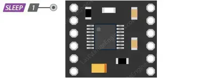
Sleep Mode Pin
The DRV8833 motor driver has a Sleep Mode pin, labeled as “SLEEP” on the board silkscreen. This pin controls the sleep mode functionality of the DRV8833. When the Sleep Mode pin is set to a specific logic level, it determines whether the motor driver is in a low-power sleep mode or an active operating mode. Here’s how the Sleep Mode pin works:
Setting SLEEP Pin LOW:
- When the SLEEP pin is pulled LOW (connected to Ground), the DRV8833 enters a low-power sleep mode. In this mode, the motor driver goes into a state of minimal power consumption, effectively disabling the H-bridges and the gate drive charge pump. All internal logic is reset, internal clocks are stopped, and all inputs are ignored.
- During sleep mode, the motor driver is effectively turned off, and it consumes very little power. This is particularly useful when the motors are not in use, allowing you to save power and increase energy efficiency in battery-powered or low-power applications.
Setting SLEEP Pin HIGH:
- When the SLEEP pin is set to a logic HIGH (connected to VCC or 5V), the DRV8833 becomes active and operational. In this state, the motor driver can receive control signals and operate the connected motors as required.
- After being in sleep mode, the DRV8833 needs a little time (up to 1 millisecond) to become fully operational again once the Sleep Mode pin is set to HIGH.

By default, the SLEEP pin is usually pulled high on the board, meaning that the DRV8833 is active and ready for operation when power is supplied. However, if you want to utilize the low-power sleep mode, you can set the SLEEP pin to LOW to put the DRV8833 in sleep mode and save power during periods of inactivity.
On the backside of the DRV8833 module, there’s a solder jumper (labeled J1). By default, J1 is closed, which means the onboard pull-up resistor is connected to the SLEEP pin, keeping the DRV8833 enabled. However, if you open J1 (disconnect the jumper), it enables the on-chip pull-down resistor, which means the DRV8833 will remain disabled by default. In this case, you’ll need to manually enable the motor driver when needed by setting the SLEEP pin to HIGH.
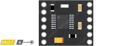
Fault Detection Pin
The DRV8833 motor driver has a Fault Detection pin, labeled as “FAULT” on the board silkscreen. This pin serves as an open-drain output that is driven low by the DRV8833 chip whenever certain fault conditions occur. The Fault Detection pin allows external monitoring of these fault conditions, which include over-current, over-temperature, or under-voltage events.
Here’s how the Fault Detection pin works:
Normal Operation:
- Under normal operating conditions, the Fault pin remains in a floating state or is left unconnected. This indicates that there are no fault events detected by the motor driver, and it is functioning correctly.
Fault Conditions:
If any of the following fault conditions occur, the DRV8833 will drive the Fault pin LOW, indicating the occurrence of a fault event:
- Over-current: The driver detects excessive current flow through the motor outputs, which may happen due to a motor stall or other issues.
- Over-temperature: The driver senses that the internal temperature has exceeded a safe operating range, possibly due to prolonged high current operation or environmental factors.
- Under-voltage: The driver detects a voltage drop below the minimum specified operating voltage, indicating a potential power supply issue.
External Pull-Up Resistor:
- To effectively monitor fault conditions using the Fault Detection pin, you need to connect an external pull-up resistor between the Fault pin and the VCC (or 5V) rail. This resistor will ensure that the pin remains in a known state when no fault is detected (i.e., it remains HIGH when no fault occurs).
- You can use a microcontroller input with its built-in pull-up resistor enabled or connect a pull-up resistor externally to achieve this.
Clearing Fault Condition:
- After a fault condition is detected, the motor driver will disable the H-bridges, and the Fault pin will be driven LOW. To clear the fault and resume normal operation, you must address the cause of the fault and then restart the motor driver by cycling its Sleep Mode pin or providing appropriate control signals.
Monitoring the Fault Detection pin allows you to implement protective measures and respond accordingly to fault events, ensuring safe and reliable motor operation in various applications.
Current limiting
The DRV8833 motor driver has the capability to actively limit the current flowing through the connected motors. Normally, this is achieved by placing a resistor between the AISEN pin and ground to set the current limit for Motor A, and another resistor between the BISEN pin and ground to set the limit for Motor B.
However, it’s important to note that the particular DRV8833 breakout board being used in this case connects the current sense pins (AISEN and BISEN) directly to ground. As a result, this specific breakout board effectively disables the current limiting feature of the DRV8833 motor driver.
In practical terms, this means that without the appropriate resistors to set the current limits, the motor driver may not actively restrict the current flowing to the connected motors. It’s essential to be aware of this limitation when using this specific DRV8833 arduino breakout board, as it may impact the performance and safety of the motor driver in certain applications.
Connecting DRV8833 Module to an Arduino
Now that we have a good understanding of the DRV8833 module, let’s proceed with connecting it to our Arduino.
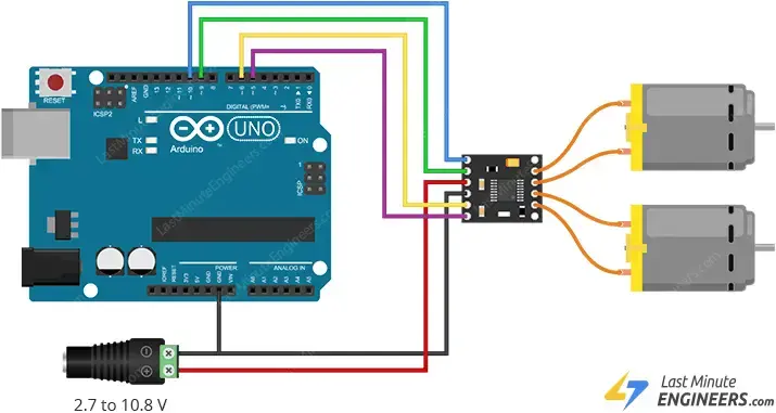
First, we need to provide power to the motors. The VCC pin on the DRV8833 module is responsible for powering the motors. Depending on the motor’s requirements (which can range from 2.7V to 10.8V), you should connect an appropriate power source. In our experiment, we are using DC gearbox motors, commonly known as “TT” motors, which are often used in two-wheel-drive robots. These motors are rated for 3 to 12V, so we will connect an external 5V power supply to the VCC pin.
Next, we’ll connect the control inputs of the DRV8833 module (IN1, IN2, IN3, and IN4) to four digital output pins (10, 9, 6, and 5) on the Arduino. It’s essential to note that all of these Arduino pins are PWM-enabled, which allows for more precise control of the motors.
We will connect one motor to terminal A (OUT1 and OUT2) and the other motor to terminal B (OUT3 and OUT4) on the DRV8833 module. It’s worth mentioning that you can swap the motor’s connections as there is no specific right or wrong way to do it.
If you wish to monitor fault conditions, such as over-current or over-temperature, you can connect the FAULT pin of the DRV8833 module to a digital pin on the Arduino. However, please remember to use an external pull-up resistor or enable the built-in pull-up resistor in the Arduino for this specific pin, as it operates as an open-drain output.
Finally, ensure that both your circuit and the Arduino share a common ground to establish a reference point for the electrical signals.
| DRV8833 Driver | Arduino |
| GND | GND |
| IN1 | 10 |
| IN2 | 9 |
| IN3 | 6 |
| IN4 | 5 |
Below is a table summarizing the pin connections for interfacing the DRV8833 motor driver with the Arduino:
Parts Required
| Component Name | Buy Now |
| Arduino Uno REV3 | Amazon |
| DRV8833 Motor Drive Module 1.5A Dual H Bridge DC | Amazon |
| Geared Motor DC3V-12V DC for Four-wheel Drive Toy Car | Amazon |
| Breadboard | Amazon |
| BOJACK 1000 Pcs 25 Values Resistor Kit 1 Ohm-1M Ohm with 5% 1/4W | Amazon |
Arduino Example Code: Controlling DC Motors with DRV8833 Motor Driver
The following Arduino sketch demonstrates how to control the speed and direction of a pair of DC motors using the DRV8833 Motor Driver. This code serves as a basis for more practical experiments and projects involving DC motors.
In this sketch, two DC motors are moved at varying rates and directions. Note that when accelerating or decelerating the motors, you may hear a humming sound, especially at lower PWM values. This is normal behavior for DC motors and nothing to be concerned about. The humming occurs because the motor requires a minimum voltage to operate.
// Define the control inputs
#define MOT_A1_PIN 10
#define MOT_A2_PIN 9
#define MOT_B1_PIN 6
#define MOT_B2_PIN 5

void setup(void)
{
  // Set all the motor control inputs to OUTPUT
  pinMode(MOT_A1_PIN, OUTPUT);
  pinMode(MOT_A2_PIN, OUTPUT);
  pinMode(MOT_B1_PIN, OUTPUT);
  pinMode(MOT_B2_PIN, OUTPUT);

  // Turn off motors - Initial state
  digitalWrite(MOT_A1_PIN, LOW);
  digitalWrite(MOT_A2_PIN, LOW);
  digitalWrite(MOT_B1_PIN, LOW);
  digitalWrite(MOT_B2_PIN, LOW);

  // Initialize the serial UART at 9600 baud
  Serial.begin(9600);
}

void loop(void)
{
  // Generate a fixed motion sequence to demonstrate the motor modes.

  // Ramp speed up.
  for (int i = 0; i < 11; i++) {
    spin_and_wait(25*i, 25*i, 500);
  }
  // Full speed forward.
  spin_and_wait(255,255,2000);

  // Ramp speed into full reverse.
  for (int i = 0; i < 21 ; i++) {
    spin_and_wait(255 - 25*i, 255 - 25*i, 500);
  }

  // Full speed reverse.
  spin_and_wait(-255,-255,2000);

  // Stop.
  spin_and_wait(0,0,2000);

  // Full speed, forward, turn, reverse, and turn for a two-wheeled base.
  spin_and_wait(255, 255, 2000);
  spin_and_wait(0, 0, 1000);
  spin_and_wait(-255, 255, 2000);
  spin_and_wait(0, 0, 1000);
  spin_and_wait(-255, -255, 2000);
  spin_and_wait(0, 0, 1000);
  spin_and_wait(255, -255, 2000);
  spin_and_wait(0, 0, 1000);
}

/// Set the current on a motor channel using PWM and directional logic.
///
/// \param pwm    PWM duty cycle ranging from -255 full reverse to 255 full forward
/// \param IN1_PIN  pin number xIN1 for the given channel
/// \param IN2_PIN  pin number xIN2 for the given channel
void set_motor_pwm(int pwm, int IN1_PIN, int IN2_PIN)
{
  if (pwm < 0) {  // reverse speeds
    analogWrite(IN1_PIN, -pwm);
    digitalWrite(IN2_PIN, LOW);

  } else { // stop or forward
    digitalWrite(IN1_PIN, LOW);
    analogWrite(IN2_PIN, pwm);
  }
}

/// Set the current on both motors.
///
/// \param pwm_A  motor A PWM, -255 to 255
/// \param pwm_B  motor B PWM, -255 to 255
void set_motor_currents(int pwm_A, int pwm_B)
{
  set_motor_pwm(pwm_A, MOT_A1_PIN, MOT_A2_PIN);
  set_motor_pwm(pwm_B, MOT_B1_PIN, MOT_B2_PIN);

  // Print a status message to the console.
  Serial.print("Set motor A PWM = ");
  Serial.print(pwm_A);
  Serial.print(" motor B PWM = ");
  Serial.println(pwm_B);
}

/// Simple primitive for the motion sequence to set a speed and wait for an interval.
///
/// \param pwm_A  motor A PWM, -255 to 255
/// \param pwm_B  motor B PWM, -255 to 255
/// \param duration delay in milliseconds
void spin_and_wait(int pwm_A, int pwm_B, int duration)
{
  set_motor_currents(pwm_A, pwm_B);
  delay(duration);
}
This sketch demonstrates various motion sequences, including ramping up and down the motor speed, moving forward and backward at full speed, stopping, and performing a predefined two-wheeled motion pattern. The function spin_and_wait sets the speed of both motors and then waits for a specified duration. The set_motor_currents function sets the PWM value for each motor channel, allowing for precise control of the motor speed and direction.
Code Explanation:
The code begins by defining the Arduino pins connected to the DRV8833’s control inputs. The pins are named MOT_A1_PIN, MOT_A2_PIN, MOT_B1_PIN, and MOT_B2_PIN and correspond to Arduino digital output pins 10, 9, 6, and 5, respectively.
// Define the control inputs
#define MOT_A1_PIN 10
#define MOT_A2_PIN 9
#define MOT_B1_PIN 6
#define MOT_B2_PIN 5
In the setup() function, the motor control pins are initialized as OUTPUT, and all motors are initially turned off by setting their control pins to LOW.
The serial communication is initialized with a baud rate of 9600, allowing data to be sent and received between the Arduino and a connected computer.
void setup(void)
{
  // Set all the motor control inputs to OUTPUT
  pinMode(MOT_A1_PIN, OUTPUT);
  pinMode(MOT_A2_PIN, OUTPUT);
  pinMode(MOT_B1_PIN, OUTPUT);
  pinMode(MOT_B2_PIN, OUTPUT);

  // Turn off motors - Initial state
  digitalWrite(MOT_A1_PIN, LOW);
  digitalWrite(MOT_A2_PIN, LOW);
  digitalWrite(MOT_B1_PIN, LOW);
  digitalWrite(MOT_B2_PIN, LOW);

  // Initialize the serial UART at 9600 baud
  Serial.begin(9600);
}
The main logic of the sketch is implemented in the loop() function. The code generates a fixed motion sequence to demonstrate different motor modes, including acceleration, deceleration, forward and reverse motion, and stopping.
// Ramp speed up.
for (int i = 0; i < 11; i++) {
  spin_and_wait(25*i, 25*i, 500);
}
// Full speed forward.
spin_and_wait(255,255,2000);

// Ramp speed into full reverse.
for (int i = 0; i < 21 ; i++) {
  spin_and_wait(255 - 25*i, 255 - 25*i, 500);
}

// Full speed reverse.
spin_and_wait(-255,-255,2000);

// Stop.
spin_and_wait(0,0,2000);
The spin_and_wait() function is called within the loop() function to execute various motor movements. This function sets the speed of both motors using PWM values and then waits for a specified duration before moving to the next motor command.
// Full speed, forward, turn, reverse, and turn for a two-wheeled base.
spin_and_wait(255, 255, 2000);
spin_and_wait(0, 0, 1000);
spin_and_wait(-255, 255, 2000);
spin_and_wait(0, 0, 1000);
spin_and_wait(-255, -255, 2000);
spin_and_wait(0, 0, 1000);
spin_and_wait(255, -255, 2000);
spin_and_wait(0, 0, 1000);
The set_motor_pwm() function is used to set the current on a motor channel using PWM and directional logic. If the PWM value is negative, the motor spins in one direction (reverse). If the PWM value is 0 or positive, the motor either stops or spins in the other direction (forward).
void set_motor_pwm(int pwm, int IN1_PIN, int IN2_PIN)
{
  if (pwm < 0) {  // reverse speeds
    analogWrite(IN1_PIN, -pwm);
    digitalWrite(IN2_PIN, LOW);

  } else { // stop or forward
    digitalWrite(IN1_PIN, LOW);
    analogWrite(IN2_PIN, pwm);
  }
}
The set_motor_currents() function sets the PWM values for both motors. It calls the set_motor_pwm() function for each motor channel (A and B) to set their respective PWM values. Additionally, it prints the current PWM values for both motors to the serial monitor.
void set_motor_currents(int pwm_A, int pwm_B)
{
  set_motor_pwm(pwm_A, MOT_A1_PIN, MOT_A2_PIN);
  set_motor_pwm(pwm_B, MOT_B1_PIN, MOT_B2_PIN);

  // Print a status message to the console.
  Serial.print("Set motor A PWM = ");
  Serial.print(pwm_A);
  Serial.print(" motor B PWM = ");
  Serial.println(pwm_B);
}
The code uses loops to ramp up and down the motor speed gradually and demonstrates various movement patterns, such as turning for a two-wheeled robot base.
Overall, this code allows the user to control the speed and direction of two DC motors using the DRV8833 Motor Driver. By changing the PWM values and durations, different motion patterns and motor behaviors can be achieved, making it suitable for various robotics and automation projects.
void spin_and_wait(int pwm_A, int pwm_B, int duration)
{
  set_motor_currents(pwm_A, pwm_B);
  delay(duration);
}
Related article
- Servo Motor Basics: How It Works and Arduino Interface Guide
- Interfacing DC Motors with Arduino using L298N Motor Driver Module
- Interfacing 28BYJ-48 Stepper Motor Arduino using ULN2003 Driver
- Step-by-Step Guide: Arduino Stepper Motor Control with DRV8825 Driver
- Step-by-Step Guide: Arduino Stepper Motor Control with A4988 Driver
- Arduino Motor Control: L293D Motor Driver for DC Motors
- Step-by-Step Guide: L293D Stepper Motor Driver with Arduino


