

This beginner’s guide will teach you how to interpret digital signals from devices such as button switches and manage digital outputs like LEDs using the ESP8266 NodeMCU board with the Arduino IDE.
Controlling Digital Outputs with ESP8266 NodeMCU
Begin by configuring the GPIO you wish to control as an OUTPUT. Utilize the pinMode() function in the following manner:
pinMode(GPIO, OUTPUT);
To manage a digital output, employ the digitalWrite() function. It requires two arguments: the GPIO (an integer) you’re addressing and the state, either HIGH or LOW.
digitalWrite(GPIO, STATE);
Refer to the ESP8266 GPIO Reference Guide for guidance on selecting appropriate GPIOs for output usage.
Reading Digital Inputs with ESP8266 NodeMCU
Begin by configuring the GPIO you wish to read as an INPUT using the pinMode() function:
pinMode(GPIO, INPUT);
To read a digital input, such as a button, utilize the digitalRead() function. It takes the GPIO (an integer) you’re referencing as its argument.
digitalRead(GPIO);
Refer to the ESP8266 GPIO Reference Guide to identify GPIOs best suited for input purposes.
Project Example
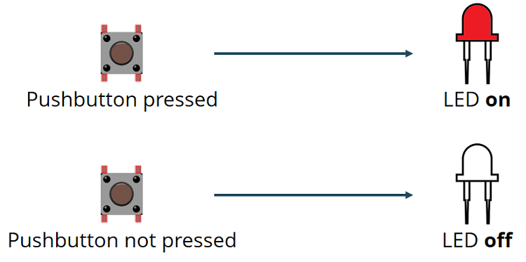
To demonstrate the utilization of digital inputs and outputs, we will construct a basic project example employing a pushbutton and an LED. We’ll monitor the pushbutton’s state and illuminate the LED accordingly, as depicted in the diagram below.
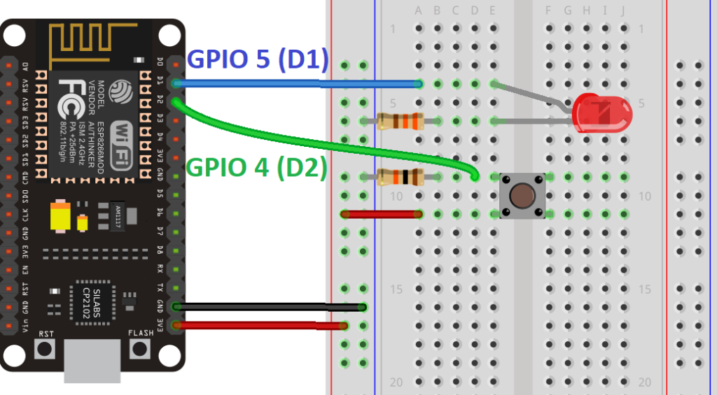
Schematic Diagram
Prior to proceeding, assemble a circuit comprising an LED and a pushbutton. Connect the LED to GPIO 5 (D1) and the pushbutton to GPIO 4 (D2).
Parts Required
| Component Name | Buy Now |
| ESP8266 NodeMCU CP2102 | Amazon |
Code
Paste the provided code into your Arduino IDE.
// set pin numbers
const int buttonPin = 4;     // the number of the pushbutton pin
const int ledPin =  5;       // the number of the LED pin

// variable for storing the pushbutton status
int buttonState = 0;

void setup() {
  // initialize the pushbutton pin as an input
  pinMode(buttonPin, INPUT);
  // initialize the LED pin as an output
  pinMode(ledPin, OUTPUT);
}

void loop() {
  // read the state of the pushbutton value
  buttonState = digitalRead(buttonPin);
  // check if the pushbutton is pressed.
  // if it is, the buttonState is HIGH
  if (buttonState == HIGH) {
    // turn LED on
    digitalWrite(ledPin, HIGH);
  } else {
    // turn LED off
    digitalWrite(ledPin, LOW);
  }
}
Code Explanation
In the ensuing lines, you define variables to assign pins:
const int buttonPin = 4;
const int ledPin = 5;
The button connects to GPIO 4, and the LED connects to GPIO 5. When employing the Arduino IDE with the ESP8266, 4 corresponds to GPIO 4, and 5 corresponds to GPIO 5.
Subsequently, you create a variable to store the button state, initially set to 0 (unpressed):
int buttonState = 0;
Within the setup(), you initialize the button as an INPUT and the LED as an OUTPUT using pinMode(), which takes the pin and mode (INPUT or OUTPUT) as arguments:
pinMode(buttonPin, INPUT);
pinMode(ledPin, OUTPUT);
In the loop(), you read the button state and adjust the LED accordingly.
In the subsequent line, you read the button state and store it in the buttonState variable, utilizing digitalRead():
buttonState = digitalRead(buttonPin);
The ensuing if statement examines if the button state is HIGH. If affirmative, it illuminates the LED by setting it to HIGH via digitalWrite(), taking ledPin and HIGH as arguments:
if (buttonState == HIGH) {
  digitalWrite(ledPin, HIGH);
}
Should the button state not be HIGH, the LED is turned off by setting it to LOW as the second argument in digitalWrite():
else {
  digitalWrite(ledPin, LOW);
}
Uploading the Code
Before clicking the upload button, navigate to Tools > Board and select the board you’re using. In my case, it’s the NodeMCU 1.0 (ESP-12 E Module). If you’re unsure about your ESP8266 model, you can opt for “Generic ESP8266 Module”.
Navigate to Tools > Port and choose the COM port to which the ESP8266 is connected. Then, click the upload button and await the “Done uploading” notification.
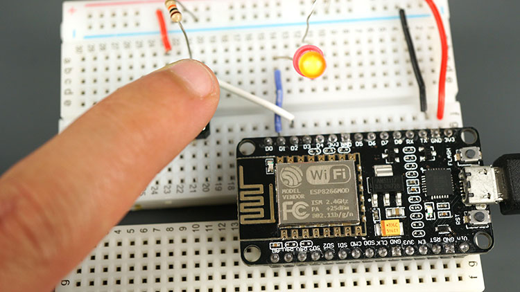
Demonstration
Once the code is uploaded, verify your circuit. The LED should illuminate when you press the pushbutton:
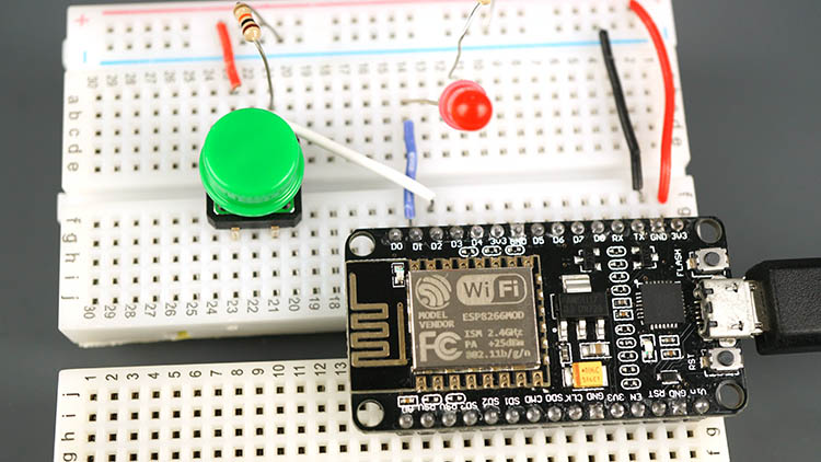
And it should turn off when you release it:
Wrapping Up
With this introductory guide, you’ve mastered the basics of reading digital inputs and controlling digital outputs with the ESP8266 using the Arduino IDE.
For further learning on reading analog inputs or outputting PWM signals, refer to the following guides:
You may also find it beneficial to consult the ESP8266 GPIO Reference, which elucidates the usage of ESP8266 GPIOs and their functions.
- Mastering ESP8266 GPIO Interrupts: Arduino IDE Configuration Tips
- Complete ESP8266 Pinout Reference: Simplify Your Hardware Connections


