
This guide demonstrates how to create PWM signals using the ESP8266 NodeMCU with the Arduino IDE. As an illustration, we’ll adjust the LED brightness by altering the duty cycle gradually.
analogWrite(pin, value). The ‘value’ parameter should be an integer ranging from 0 to 255.For ESP8266 versions preceding 3.0, the default PWM range spans from 0 to 1023. However, you can modify this range by invoking analogWriteRange(new_range).
You may also find it beneficial to explore additional resources on PWM:
Before commencing this tutorial, ensure that you have installed the ESP8266 add-on in your Arduino IDE. If not, follow the instructions outlined in the subsequent tutorial:
ESP8266 NodeMCU PWM (Pulse-Width Modulation)
The ESP8266 NodeMCU employs Pulse-Width Modulation (PWM) to manage its GPIOs. While these pins can only output either 0V or 3.3V directly, PWM enables the simulation of intermediate voltage levels. This technique facilitates the creation of varying LED brightness levels for your project.
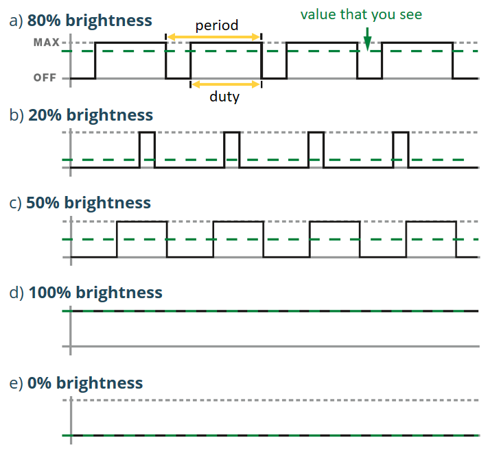
By rapidly toggling the LED voltage between HIGH and LOW, the human eye perceives the average brightness rather than the rapid switching. This modulation technique achieves different brightness levels by adjusting the duty cycle, which represents the fraction of time the LED remains in the HIGH state within each cycle.
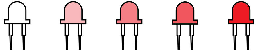
A duty cycle of 50 percent corresponds to 50 percent LED brightness. A duty cycle of 0 turns off the LED completely, while a duty cycle of 100 fully illuminates it. Altering the duty cycle allows for the production of different brightness levels.
analogWrite()
The analogWrite() function is utilized to generate a PWM (Pulse-Width Modulation) signal on a specified pin. Here’s how it works:
analogWrite(pin, value);
pin: PWM functionality is available on pins 0 to 16.value: Should fall within the range from 0 to the default PWM range, which is 255. When the value is set to 0, PWM on that pin is disabled. A value of 255 corresponds to a 100% duty cycle.
You have the flexibility to adjust the PWM range by invoking:
analogWriteRange(new_range);
By default, the PWM frequency for ESP8266 is set at 1kHz. However, you can modify this frequency using:
analogWriteFreq(new_frequency);
Valid frequency values range from 100Hz to 40000Hz.
Dimming LED with PWM on ESP8266 NodeMCU
This section presents a basic example demonstrating how to dim an LED using PWM, providing insight into its application in your projects. To proceed, gather the following components:
Parts Required
| Component Name | Buy Now |
| ESP8266 NodeMCU CP2102 | Amazon |
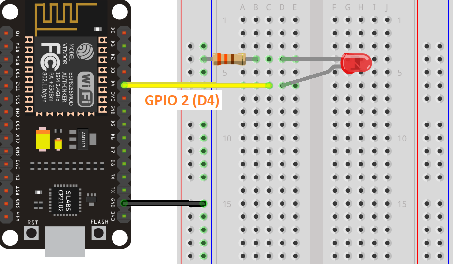
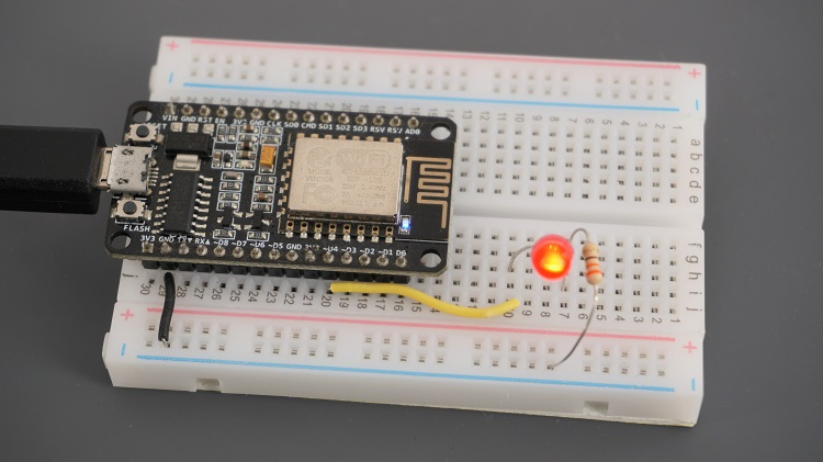
Schematic
Once the code is uploaded, connect an LED to your ESP8266 following the schematic diagram below. While we’ve connected the LED to GPIO 2, you can utilize any other GPIO pin as per your requirements.
ESP8266 NodeMCU PWM Code
Paste the code into your Arduino IDE and upload it to your ESP8266.
const int ledPin = 2;

void setup() {

}

void loop() {
  // increase the LED brightness
  for(int dutyCycle = 0; dutyCycle < 255; dutyCycle++){
    // changing the LED brightness with PWM
    analogWrite(ledPin, dutyCycle);
    delay(1);
  }

  // decrease the LED brightness
  for(int dutyCycle = 255; dutyCycle > 0; dutyCycle--){
    // changing the LED brightness with PWM
    analogWrite(ledPin, dutyCycle);
    delay(1);
  }
}
Code Explanation
Read on to understand the code’s functionality, or skip ahead to the next section.
The code begins by defining the pin to which the LED is connected. In this instance, the LED is linked to GPIO 2 (D4).
const int ledPin = 2;
Within the loop(), the duty cycle varies between 0 and 255 to increase LED brightness.
for(int dutyCycle = 0; dutyCycle < 255; dutyCycle++){
  // changing the LED brightness with PWM
  analogWrite(ledPin, dutyCycle);
  delay(1);
}
Subsequently, it varies between 255 and 0 to decrease brightness.
for(int dutyCycle = 255; dutyCycle > 0; dutyCycle--){
  // changing the LED brightness with PWM
  analogWrite(ledPin, dutyCycle);
  delay(1);
}
To control the LED brightness, utilize the analogWrite() function. Specify the GPIO for the PWM signal and a value ranging from 0 to 255 to set the duty cycle.
Uploading the Code
Open your Arduino IDE and navigate to Tools > Board. Choose your ESP8266 model from the list. (For ESP-01, select “Generic ESP8266 Module”.)
Proceed to Tools > Port and select the COM port to which your ESP8266 is connected.
If you’re utilizing an ESP-01, you’ll require an FTDI programmer or Serial Adapter to upload the code. Below are the connections you should establish:
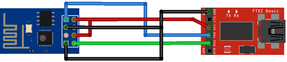
| ESP-01 | FTDI Programmer |
| RX | TX |
| TX | RX |
| CH_PD | 3.3V |
| GPIO 0 | GND |
| VCC | 3.3V |
| GND | GND |
Demonstration
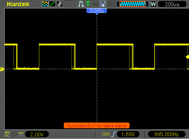
Once your sketch is uploaded, observe how the LED linked to GPIO 2 gradually varies in brightness.
For a detailed insight into the PWM signal’s evolution, consider connecting GPIO 2 to an oscilloscope.
Wrapping Up
We trust you’ve found this guide on ESP8266 PWM usage beneficial. Apart from regulating LED brightness, PWM proves handy in controlling the speed of DC motors.
Explore our other projects for further experimentation!
- Mastering ESP8266 GPIO Interrupts: Arduino IDE Configuration Tips
- Complete ESP8266 Pinout Reference: Simplify Your Hardware Connections
- Beginner’s Guide: ESP8266 NodeMCU Digital Input and Output Setup


