

This guide explains how to utilize deep sleep mode with the ESP8266 (NodeMCU) using the Arduino IDE. We’ll discuss two methods: deep sleep with timer wake up and deep sleep with external wake up using the reset (RST) pin.
ESP.deepSleep(uS), passing the sleep duration in microseconds as an argument. Ensure that GPIO 16 is connected to the reset (RST) pin to enable wake-up functionality.For deep sleep mode with an indefinite duration, utilize ESP.deepSleep(0). The ESP8266 will awaken when the RST pin receives a LOW signal.
Parts Required
| Component Name | Buy Now |
| ESP8266 NodeMCU CP2102 | Amazon |
Introducing Deep Sleep Mode
If you’ve embarked on a project with a battery-powered ESP8266 board or simply connected your ESP8266 NodeMCU board to a power bank, you may have noticed that the battery drains quickly, especially when utilizing Wi-Fi.
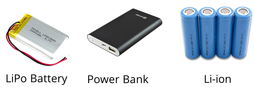
By activating deep sleep mode on your ESP8266, you can significantly reduce power consumption, thereby extending the lifespan of your batteries.
Deep sleep mode on the ESP8266 entails minimizing power-intensive activities such as Wi-Fi usage while maintaining enough functionality to awaken the processor when necessary events occur.
Sleep Modes Overview
There exist three distinct sleep modes: modem sleep, light sleep, and deep sleep. The table below delineates the discrepancies among these modes (data derived from the ESP8266 datasheet).
| Item | Modem-sleep | Light-sleep | Deep-sleep |
| Wi-Fi | OFF | OFF | OFF |
| System clock | ON | OFF | OFF |
| RTC | ON | ON | ON |
| CPU | ON | Pending | OFF |
| Substrate current | 15 mA | 0.4 mA | ~20 uA |
| Average current (DTIM = 1) | 16.2 mA | 1.8 mA | – |
| Average current (DTIM = 3) | 15.4 mA | 0.9 mA | – |
| Average current (DTIM = 10) | 15.2 mA | 0.55 mA | – |
Each sleep mode serves a unique purpose and should be employed according to the specific requirements of the application.
In this discussion, we’ll delve into deep sleep mode. In this state, all functionalities are deactivated except for the Real-Time Clock (RTC), which enables the ESP8266 to maintain time tracking.

Deep sleep mode stands as the most power-efficient option, with the ESP chip drawing approximately 20uA. However, if you’re utilizing a fully-featured development board equipped with built-in programmers, LEDs, etc., achieving such a low-power state may not be feasible.
Deep Sleep Example
In a deep sleep scenario, an application typically follows this sequence:
- The ESP8266 establishes a Wi-Fi connection.
- The ESP8266 executes a task (such as sensor reading or publishing an MQTT message).
- It enters a predefined sleep duration.
- The ESP8266 awakens.
- This cycle repeats continuously.
Wake-Up Mechanisms
Upon entering deep sleep mode, the ESP8266 can be awakened through various means:
- Timer Wake-Up: The ESP8266 autonomously reactivates after a set time interval.
- External Wake-Up: Activation occurs when the RST button is pressed, prompting the ESP8266 to restart.
For projects emphasizing low power consumption, the ESP32 board may be preferable, offering additional deep sleep modes and wake-up sources.
ESP8266 Deep Sleep with Timer Wake-Up
To enable timer wake-up with the ESP8266, you must establish a connection between the RST pin and GPIO 16, which is designated as D0 on a NodeMCU board. Refer to the following schematic diagram:
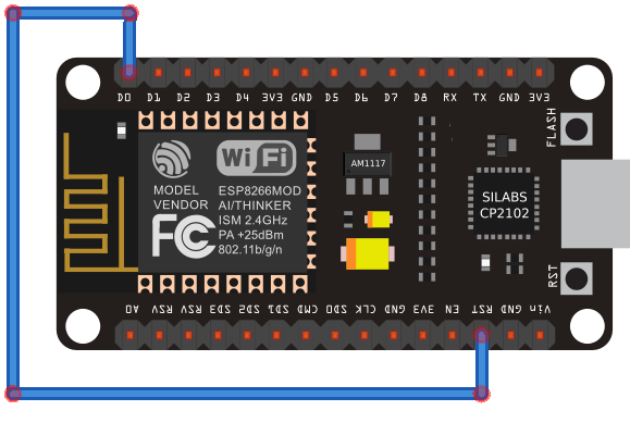
Ensure to link the RST pin to GPIO 16 only after uploading the code.
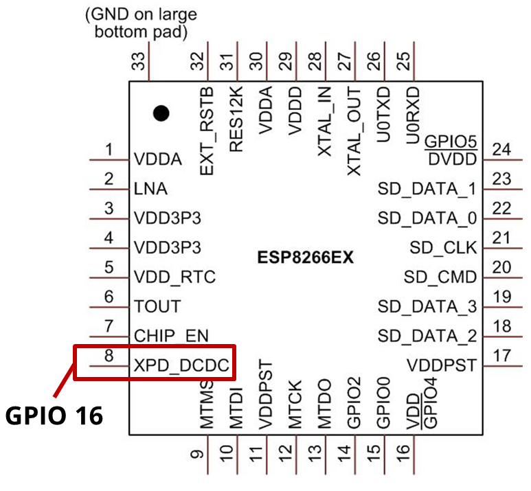
Upon examining the NodeMCU pinout, you’ll notice that GPIO 16 possesses a special WAKE feature.
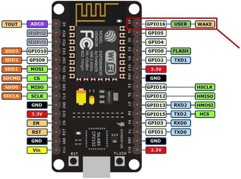
Under normal operation, the RST pin of the ESP8266 remains in a HIGH state. However, when it receives a LOW signal, it triggers a microcontroller restart.
By configuring a deep sleep timer with the ESP8266, GPIO 16 emits a LOW signal upon timer expiration. Consequently, connecting GPIO 16 to the RST pin enables the ESP8266 to awaken after a specified time interval.
ESP8266 NodeMCU Timer Wake-Up Sketch
Assuming you’ve installed the ESP8266 add-on for the Arduino IDE (instructions on how to install the ESP8266 Board in Arduino IDE), navigate to Tools and choose “NodeMCU (ESP-12E Module)”. Below is the code required to upload to your ESP:
void setup() {
  Serial.begin(115200);
  Serial.setTimeout(2000);

  // Wait for serial to initialize.
  while(!Serial) { }

  // Deep sleep mode for 30 seconds, the ESP8266 wakes up by itself when GPIO 16 (D0 in NodeMCU board) is connected to the RESET pin
  Serial.println("I'm awake, but I'm going into deep sleep mode for 30 seconds");
  ESP.deepSleep(30e6);

  // Deep sleep mode until RESET pin is connected to a LOW signal (for example pushbutton or magnetic reed switch)
  //Serial.println("I'm awake, but I'm going into deep sleep mode until RESET pin is connected to a LOW signal");
  //ESP.deepSleep(0);
}

void loop() {
}
In this instance, a message is printed in the Serial Monitor:
Serial.println("I'm awake, but I'm going into deep sleep mode until RESET pin is connected to a LOW signal");
Subsequently, the ESP8266 enters sleep mode for 30 seconds:
ESP.deepSleep(30e6);
To activate deep sleep mode on the ESP8266, employ ESP.deepsleep(uS) and input the sleep duration in microseconds. In this scenario, 30e6 corresponds to 30000000 microseconds, equivalent to 30 seconds.
After uploading the code, press the RST button to execute the code, then connect RST to GPIO 16. The ESP8266 should awaken every 30 seconds and print a message in the Serial Monitor as depicted below.
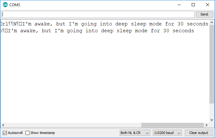
This example merely prints a message in the Serial Monitor, but in practical applications, you would perform a meaningful task such as making a request or publishing sensor readings.
ESP-01 Timer Wake-Up Circuit
If you wish to replicate a similar setup with an ESP-01 board, you must solder a wire as depicted below. That minute pin represents GPIO 16 and must connect to the RST pin.
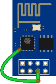
However, the pins are exceedingly small, making it challenging to solder a wire to GPIO 16 on the ESP-01… Therefore, for this wake-up mode, it’s advisable to use the NodeMCU board or a bare ESP12-E chip.
ESP8266 Deep Sleep with External Wake-Up
The ESP8266 can also be awakened externally, such as by pressing a button or activating a reed switch. Simply put the ESP8266 into deep sleep mode indefinitely, then set the RST pin to LOW to rouse it.
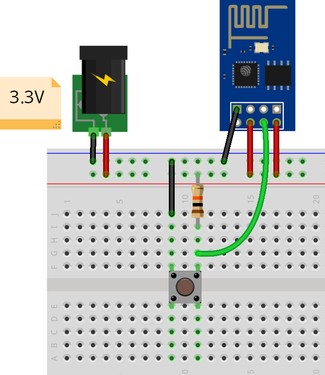
To validate this configuration, connect a pushbutton to your ESP8266 board as depicted in the subsequent schematic diagram. Pressing the pushbutton causes the RST pin to transition to a LOW state.
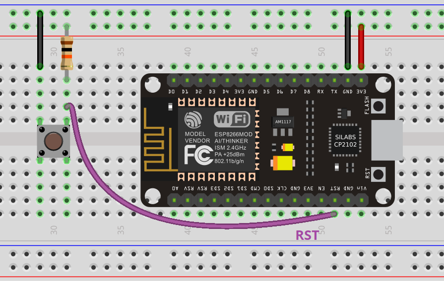
If you’re utilizing an ESP-01, refer to the alternate diagram below.
ESP8266 External Wake-Up Sketch
Subsequently, upload the provided code to your ESP8266 board.
void setup() {
  Serial.begin(115200);
  Serial.setTimeout(2000);

  // Wait for serial to initialize.
  while(!Serial) { }

  // Deep sleep mode for 30 seconds, the ESP8266 wakes up by itself when GPIO 16 (D0 in NodeMCU board) is connected to the RESET pin
  //Serial.println("I'm awake, but I'm going into deep sleep mode for 30 seconds");
  //ESP.deepSleep(30e6);

  // Deep sleep mode until RESET pin is connected to a LOW signal (for example pushbutton or magnetic reed switch)
  Serial.println("I'm awake, but I'm going into deep sleep mode until RESET pin is connected to a LOW signal");
  ESP.deepSleep(0);
}

void loop() {
}
This code places the ESP8266 in deep sleep mode for an unspecified duration. To achieve this, pass 0 as an argument to the deepSleep() function:
ESP.deepSleep(0);
The ESP will solely awaken when a reset event occurs. In this instance, it’s initiated by pressing a pushbutton that grounds the RST pin.
Upon pressing the pushbutton, the ESP8266 awakens, executes the programmed task, and returns to sleep until another reset event is triggered.
Current Measurement
While the board is in deep sleep mode, utilize a multimeter to measure the current consumption and determine the power drain.
Position your multimeter probes as follows.
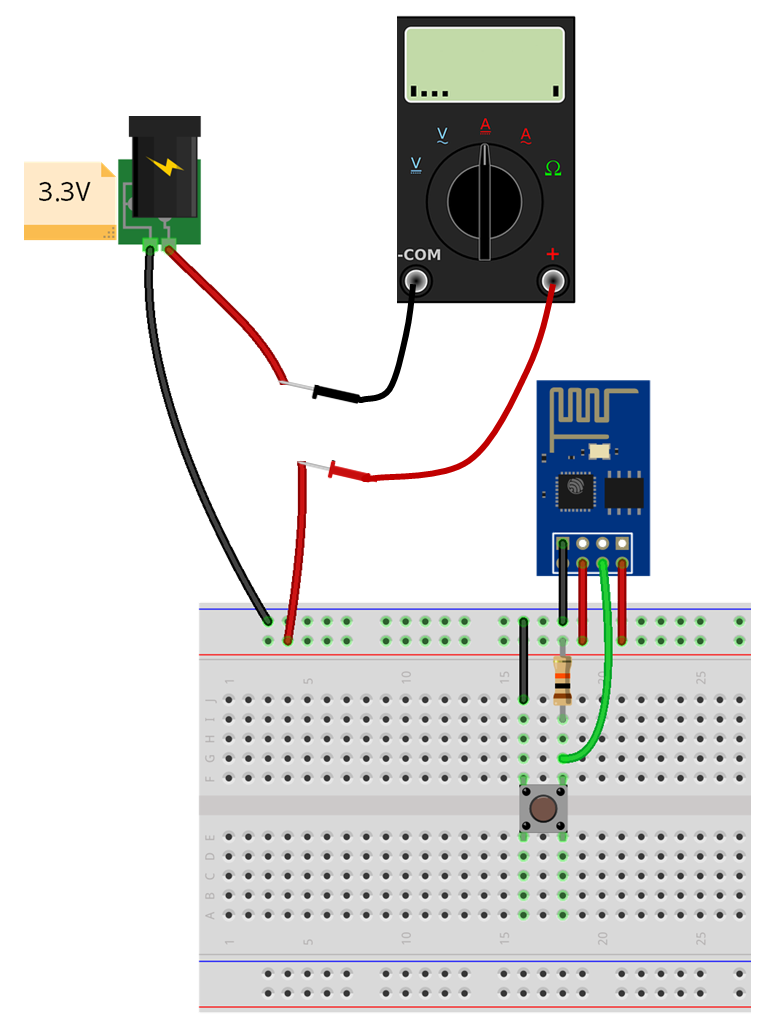
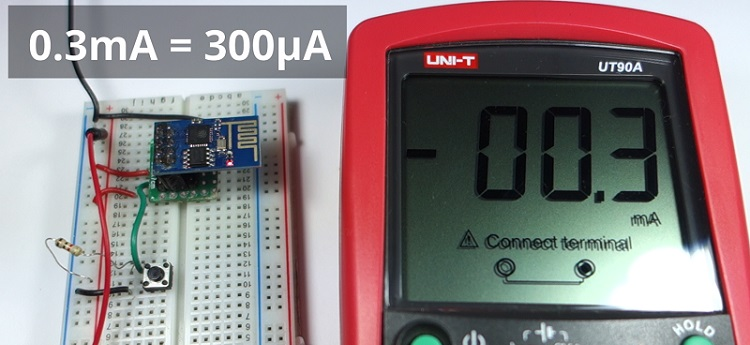
In deep sleep mode, the ESP-01 only consumes 0.3mA, approximately 300uA.
It’s important to note that during regular usage with Wi-Fi, the ESP8266 can consume between 50mA and 170mA.
Wrapping up
With knowledge of the deepSleep() function, your battery-powered projects can enjoy extended longevity.
Explore additional ESP8266 projects you might find interesting:
- Mastering ESP8266 GPIO Interrupts: Arduino IDE Configuration Tips
- Complete ESP8266 Pinout Reference: Simplify Your Hardware Connections
- Beginner’s Guide: ESP8266 NodeMCU Digital Input and Output Setup
- Arduino IDE Tutorial: ESP8266 NodeMCU PWM for LED Dimming (Analog Output)


