

Employing a relay alongside the ESP8266 presents an excellent method for remotely managing AC household appliances. This guide elucidates the process of controlling a relay module using the ESP8266 NodeMCU. We’ll delve into the functionality of a relay module, the steps to connect it to the ESP8266, and the creation of a web server for remote relay control, accommodating multiple relays as needed.
Introducing Relays
A relay functions as an electrically operated switch, akin to any other switch, capable of being toggled between on and off states, thereby either allowing or halting the flow of current. It can be manipulated using low voltages, such as the 3.3V output provided by the ESP8266 GPIOs, enabling control over higher voltages like 12V, 24V, or mains voltage (230V in Europe and 120V in the US).
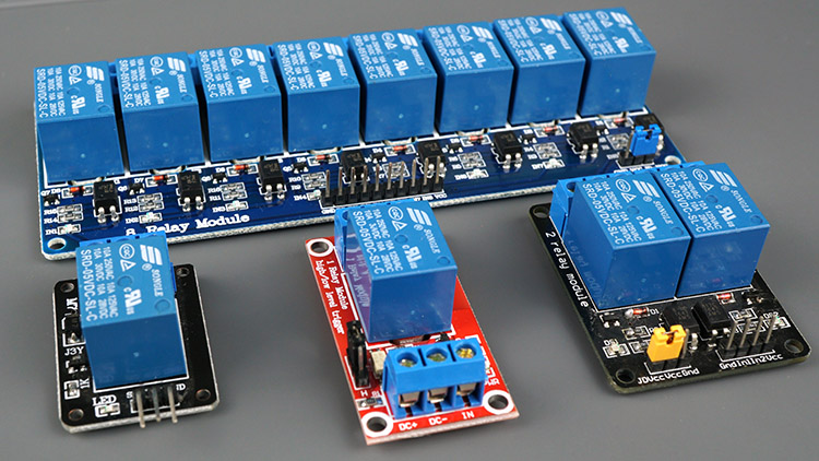
1, 2, 4, 8, 16 Channels Relay Modules
Various relay modules feature differing numbers of channels. These modules are available with one, two, four, eight, and even sixteen channels. The quantity of channels dictates the number of outputs that can be regulated.
Certain relay modules are designed to operate with either 5V or 3.3V to power their electromagnets. Both options are compatible with the ESP8266 – users can utilize either the Vin pin (providing 5V) or the 3.3V pin.
Moreover, some modules include built-in optocouplers, introducing an additional protective “layer” by optically isolating the ESP8266 from the relay circuit.
Parts Required
Relay Pinout
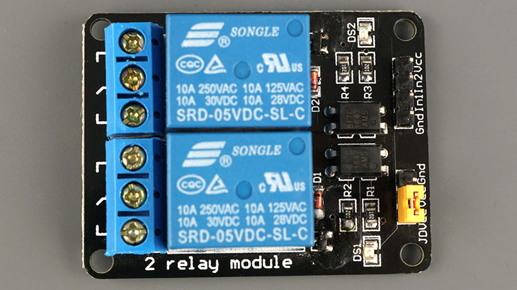
To illustrate, let’s examine the pinout of a 2-channel relay module. Utilizing a relay module with a different number of channels follows a similar setup.
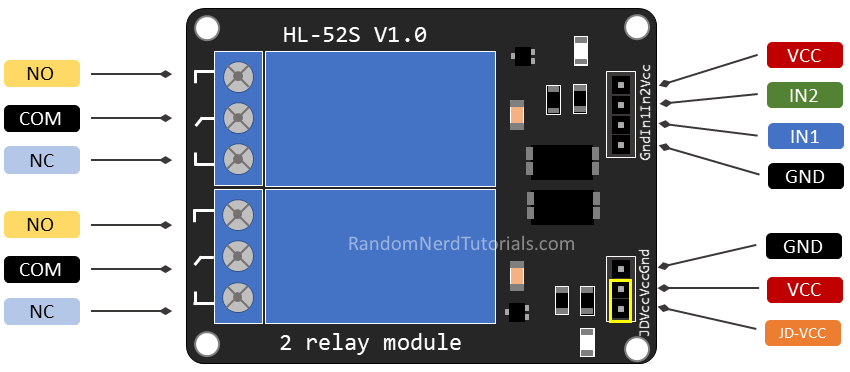
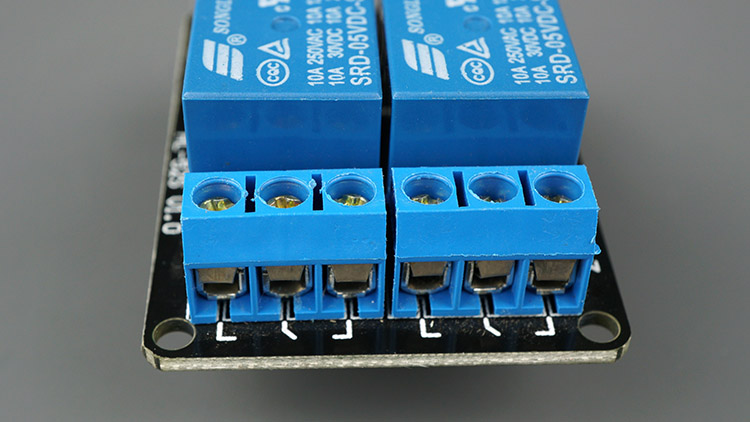
On the left side of the relay module are two connectors, each featuring three sockets for high-voltage connections. Meanwhile, the pins on the right side, designated for low-voltage, connect to the ESP8266 GPIOs.
Mains Voltage Connections
The depicted relay module exhibits two connectors, each equipped with three sockets: common (COM), normally closed (NC), and normally open (NO).
- COM: This is where the current intended for control (mains voltage) is connected.
- NC (Normally Closed): In this configuration, the relay remains closed by default. The NC and COM pins are linked, allowing current flow unless a signal is sent from the ESP8266 to the relay module, opening the circuit and halting the current flow.
- NO (Normally Open): In contrast, the normally open configuration entails no connection between the NO and COM pins. Hence, the circuit remains open until a signal from the ESP8266 is sent to close it.
Control Pins
The low-voltage side features a set of four pins and another set of three pins. The first set includes VCC and GND for powering the module, along with input 1 (IN1) and input 2 (IN2) for controlling the bottom and top relays, respectively.
For relay modules with only one channel, there will be a single IN pin. Conversely, modules with multiple channels will have corresponding IN pins.
The signal sent to the IN pins determines the relay’s activation. The relay triggers when the input drops below approximately 2V, resulting in the following scenarios:
- Normally Closed configuration (NC):
- HIGH signal – current is flowing
- LOW signal – current is not flowing
- Normally Open configuration (NO):
- HIGH signal – current is not flowing
- LOW signal – current is flowing
You should use a normally closed configuration when the current should be flowing most of the times, and you only want to stop it occasionally.
Use a normally open configuration when you want the current to flow occasionally (for example, turn on a lamp occasionally).
Power Supply Selection
The second pin set comprises GND, VCC, and JD-VCC pins. The JD-VCC pin powers the relay’s electromagnet. Notably, the module includes a jumper cap connecting the VCC and JD-VCC pins; while shown as yellow here, yours may differ in color.
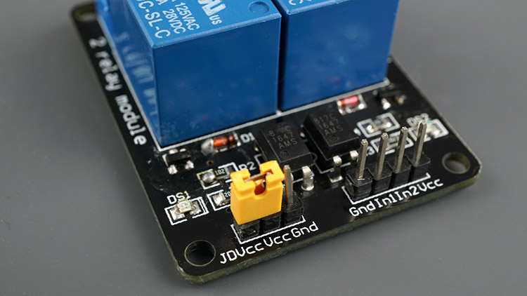
With the jumper cap in place, the VCC and JD-VCC pins are interconnected. Consequently, the relay electromagnet draws power directly from the ESP8266, eliminating physical isolation between the relay module and the ESP8266 circuits.
Removing the jumper cap necessitates an independent power source to energize the relay’s electromagnet through the JD-VCC pin. This configuration physically isolates the relays from the ESP8266 via the module’s built-in optocoupler, safeguarding the ESP8266 against electrical spikes.
Best ESP8266 Pins for Relay Usage
Certain ESP8266 pins emit a 3.3V signal during boot-up, which can pose issues if relays or other peripherals are attached to those GPIOs.
Moreover, some pins necessitate being either pulled HIGH or LOW for ESP8266 boot-up.
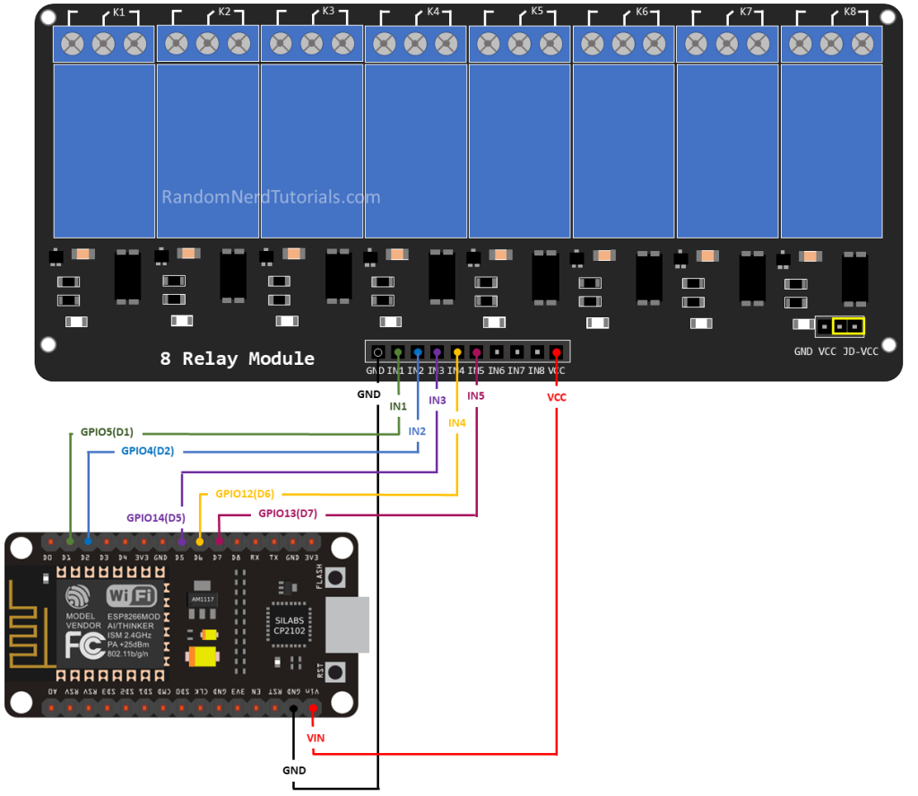
Considering these factors, the most secure ESP8266 pins for relay usage are: GPIO 5, GPIO 4, GPIO 14, GPIO 12, and GPIO 13.
Connecting a Relay Module to the ESP8266 NodeMCU Board
Follow the diagram below to wire the relay module to the ESP8266. The diagram illustrates the connection for a 2-channel relay module; wiring for a different number of channels follows a similar pattern.
Alternatively, you can utilize a 12V power source to operate 12V appliances.
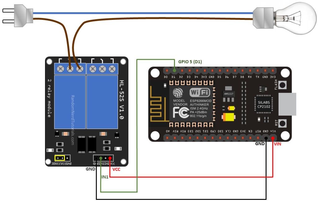
In this instance, we’re controlling a lamp. Since we only intend to illuminate the lamp occasionally, it’s preferable to employ a normally open configuration.
We’re linking the IN1 pin to GPIO 5, though any other suitable GPIO can be utilized. Refer to the ESP8266 GPIO Reference Guide for more options.
Controlling a Relay Module with the ESP8266 NodeMCU – Arduino Sketch
The code for managing a relay with the ESP8266 is as straightforward as handling an LED or any other output. In this example, since we’re utilizing a normally open configuration, we must transmit a LOW signal to enable current flow and a HIGH signal to halt it.
The following code will illuminate your lamp for 10 seconds and then deactivate it for another 10 seconds.
const int relay = 5;

void setup() {
  Serial.begin(115200);
  pinMode(relay, OUTPUT);
}

void loop() {
  // Normally Open configuration, send LOW signal to let current flow
  // (if you're usong Normally Closed configuration send HIGH signal)
  digitalWrite(relay, LOW);
  Serial.println("Current Flowing");
  delay(5000);

  // Normally Open configuration, send HIGH signal stop current flow
  // (if you're usong Normally Closed configuration send LOW signal)
  digitalWrite(relay, HIGH);
  Serial.println("Current not Flowing");
  delay(5000);
}
Code Explanation
Firstly, specify the pin to which the relay IN pin is connected.
const int relay = 5;
Within the setup() function, designate the relay as an output.
pinMode(relay, OUTPUT);
Inside the loop(), initiate a LOW signal to enable current flow, thereby illuminating the lamp.
digitalWrite(relay, LOW);
If employing a normally closed configuration, issue a HIGH signal to illuminate the lamp. Then, pause for 5 seconds.
delay(5000);
Cease the current flow by transmitting a HIGH signal to the relay pin. Alternatively, if utilizing a normally closed configuration, transmit a LOW signal to halt the current flow.
digitalWrite(relay, HIGH);
Control Multiple Relays with ESP8266 NodeMCU Web Server
This section presents a web server example enabling control of numerous relays via a web interface, whether configured as normally open or normally closed. Simply adjust a few lines of code to specify the number of relays and their pin assignments.
To construct this web server, we utilize the ESPAsyncWebServer library.
Installing the ESPAsyncWebServer library
Follow these steps to install the ESPAsyncWebServer library:
- Click here to download the ESPAsyncWebServer library. This should result in a .zip folder in your Downloads directory.
- Unzip the .zip folder to obtain the ESPAsyncWebServer-master folder.
- Rename the folder from ESPAsyncWebServer-master to ESPAsyncWebServer.
- Move the ESPAsyncWebServer folder to the libraries directory of your Arduino IDE installation.
Alternatively, within your Arduino IDE, navigate to Sketch > Include Library > Add .ZIP library… and select the downloaded library.
Installing the ESPAsyncTCP Library for ESP8266
The ESPAsyncWebServer library necessitates the ESPAsyncTCP library for operation. Follow these steps to install the required library:
- Click here to download the ESPAsyncTCP library, resulting in a .zip folder in your Downloads directory.
- Unzip the .zip folder to obtain the ESPAsyncTCP-master folder.
- Rename the folder from ESPAsyncTCP-master to ESPAsyncTCP.
- Move the ESPAsyncTCP folder to the libraries directory of your Arduino IDE installation.
- Finally, reopen your Arduino IDE.
Alternatively, within your Arduino IDE, navigate to Sketch > Include Library > Add .ZIP library… and select the downloaded library.
Once the necessary libraries are installed, copy the provided code into your Arduino IDE.
// Import required libraries
#include "ESP8266WiFi.h"
#include "ESPAsyncWebServer.h"

// Set to true to define Relay as Normally Open (NO)
#define RELAY_NO    true

// Set number of relays
#define NUM_RELAYS  5

// Assign each GPIO to a relay
int relayGPIOs[NUM_RELAYS] = {5, 4, 14, 12, 13};

// Replace with your network credentials
const char* ssid = "REPLACE_WITH_YOUR_SSID";
const char* password = "REPLACE_WITH_YOUR_PASSWORD";

const char* PARAM_INPUT_1 = "relay";
const char* PARAM_INPUT_2 = "state";

// Create AsyncWebServer object on port 80
AsyncWebServer server(80);

const char index_html[] PROGMEM = R"rawliteral(
<!DOCTYPE HTML><html>
<head>
  <meta name="viewport" content="width=device-width, initial-scale=1">
  <style>
    html {font-family: Arial; display: inline-block; text-align: center;}
    h2 {font-size: 3.0rem;}
    p {font-size: 3.0rem;}
    body {max-width: 600px; margin:0px auto; padding-bottom: 25px;}
    .switch {position: relative; display: inline-block; width: 120px; height: 68px}
    .switch input {display: none}
    .slider {position: absolute; top: 0; left: 0; right: 0; bottom: 0; background-color: #ccc; border-radius: 34px}
    .slider:before {position: absolute; content: ""; height: 52px; width: 52px; left: 8px; bottom: 8px; background-color: #fff; -webkit-transition: .4s; transition: .4s; border-radius: 68px}
    input:checked+.slider {background-color: #2196F3}
    input:checked+.slider:before {-webkit-transform: translateX(52px); -ms-transform: translateX(52px); transform: translateX(52px)}
  </style>
</head>
<body>
  <h2>ESP Web Server</h2>
  %BUTTONPLACEHOLDER%
<script>function toggleCheckbox(element) {
  var xhr = new XMLHttpRequest();
  if(element.checked){ xhr.open("GET", "/update?relay="+element.id+"&state=1", true); }
  else { xhr.open("GET", "/update?relay="+element.id+"&state=0", true); }
  xhr.send();
}</script>
</body>
</html>
)rawliteral";

// Replaces placeholder with button section in your web page
String processor(const String& var){
  //Serial.println(var);
  if(var == "BUTTONPLACEHOLDER"){
    String buttons ="";
    for(int i=1; i<=NUM_RELAYS; i++){
      String relayStateValue = relayState(i);
      buttons+= "<h4>Relay #" + String(i) + " - GPIO " + relayGPIOs[i-1] + "</h4><label class=\"switch\"><input type=\"checkbox\" onchange=\"toggleCheckbox(this)\" id=\"" + String(i) + "\" "+ relayStateValue +"><span class=\"slider\"></span></label>";
    }
    return buttons;
  }
  return String();
}

String relayState(int numRelay){
  if(RELAY_NO){
    if(digitalRead(relayGPIOs[numRelay-1])){
      return "";
    }
    else {
      return "checked";
    }
  }
  else {
    if(digitalRead(relayGPIOs[numRelay-1])){
      return "checked";
    }
    else {
      return "";
    }
  }
  return "";
}

void setup(){
  // Serial port for debugging purposes
  Serial.begin(115200);

  // Set all relays to off when the program starts - if set to Normally Open (NO), the relay is off when you set the relay to HIGH
  for(int i=1; i<=NUM_RELAYS; i++){
    pinMode(relayGPIOs[i-1], OUTPUT);
    if(RELAY_NO){
      digitalWrite(relayGPIOs[i-1], HIGH);
    }
    else{
      digitalWrite(relayGPIOs[i-1], LOW);
    }
  }

  // Connect to Wi-Fi
  WiFi.begin(ssid, password);
  while (WiFi.status() != WL_CONNECTED) {
    delay(1000);
    Serial.println("Connecting to WiFi..");
  }

  // Print ESP8266 Local IP Address
  Serial.println(WiFi.localIP());

  // Route for root / web page
  server.on("/", HTTP_GET, [](AsyncWebServerRequest *request){
    request->send_P(200, "text/html", index_html, processor);
  });

  // Send a GET request to <ESP_IP>/update?relay=<inputMessage>&state=<inputMessage2>
  server.on("/update", HTTP_GET, [] (AsyncWebServerRequest *request) {
    String inputMessage;
    String inputParam;
    String inputMessage2;
    String inputParam2;
    // GET input1 value on <ESP_IP>/update?relay=<inputMessage>
    if (request->hasParam(PARAM_INPUT_1) & request->hasParam(PARAM_INPUT_2)) {
      inputMessage = request->getParam(PARAM_INPUT_1)->value();
      inputParam = PARAM_INPUT_1;
      inputMessage2 = request->getParam(PARAM_INPUT_2)->value();
      inputParam2 = PARAM_INPUT_2;
      if(RELAY_NO){
        Serial.print("NO ");
        digitalWrite(relayGPIOs[inputMessage.toInt()-1], !inputMessage2.toInt());
      }
      else{
        Serial.print("NC ");
        digitalWrite(relayGPIOs[inputMessage.toInt()-1], inputMessage2.toInt());
      }
    }
    else {
      inputMessage = "No message sent";
      inputParam = "none";
    }
    Serial.println(inputMessage + inputMessage2);
    request->send(200, "text/plain", "OK");
  });
  // Start server
  server.begin();
}

void loop() {

}
Define Relay Configuration
Adjust the following variable to specify whether your relays are configured as normally open (NO) or normally closed (NC). Set the RELAY_NO variable to true for normally open or false for normally closed.
#define RELAY_NO true
Define Number of Relays (Channels)
You can determine the number of relays you wish to manage by setting the NUM_RELAYS variable. For illustrative purposes, we’ve set it to 5.
#define NUM_RELAYS 5
Define Relays Pin Assignment
Within the subsequent array variable, designate the ESP8266 GPIOs responsible for controlling the relays.
int relayGPIOs[NUM_RELAYS] = {5, 4, 14, 12, 13};
The quantity of relays specified in the NUM_RELAYS variable must correspond to the number of GPIOs allocated in the relayGPIOs array.
Network Credentials
Input your network credentials into the following variables.
const char* ssid     = "REPLACE_WITH_YOUR_SSID";
const char* password = "REPLACE_WITH_YOUR_PASSWORD";
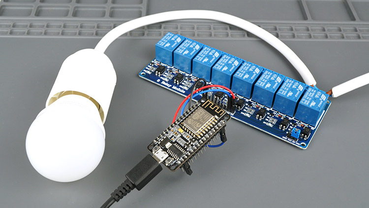
Wiring 8 Channel Relay to ESP8266 NodeMCU
To demonstrate, we’ll be controlling 5 relay channels. Connect the ESP8266 NodeMCU board to the relay module according to the schematic diagram provided.
Demonstration
Once you’ve made the necessary adjustments, upload the code to your ESP8266.
Open the Serial Monitor at a baud rate of 115200 and press the ESP8266 RST button to obtain its IP address.
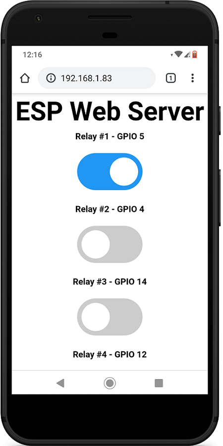
Then, within your local network, open a browser and enter the ESP8266 IP address to access the web server.
You should see a display with buttons corresponding to the number of relays defined in your code.
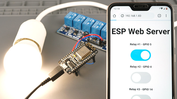
Now, you can utilize these buttons to remotely control your relays using your smartphone.
Wrapping Up
Employing relays with the ESP8266 provides an effective means of remotely controlling AC household appliances. You can also explore our other guide on controlling a Relay Module with ESP32.
Controlling a relay with the ESP8266 is as straightforward as managing any other output; simply transmit HIGH and LOW signals as you would to control an LED.
You can utilize our other web server examples designed for controlling outputs to manage relays. Just be mindful of the configuration you’re employing. If utilizing a normally open configuration, note that the relay operates with inverted logic. Below are some web server examples you can use to control your relay:
- Mastering ESP8266 GPIO Interrupts: Arduino IDE Configuration Tips
- Complete ESP8266 Pinout Reference: Simplify Your Hardware Connections
- Beginner’s Guide: ESP8266 NodeMCU Digital Input and Output Setup
- Arduino IDE Tutorial: ESP8266 NodeMCU PWM for LED Dimming (Analog Output)
- NodeMCU Deep Sleep: Enhancing ESP8266 Power Efficiency


