

We will adapt a commercial motion sensor, which operates on mains voltage, for this project. The modification involves integrating an ESP8266 to record data upon detecting motion. This data will then be transmitted to Node-RED via the MQTT communication protocol. Power for the ESP8266 will be supplied through the motion sensor’s phase-out wire using the HLK-PM03 AC/DC converter.
Parts Required
Project Overview
This project consists of three main parts:
- Building the circuit
- Writing and uploading the ESP8266 code
- Creating the Node-RED flow
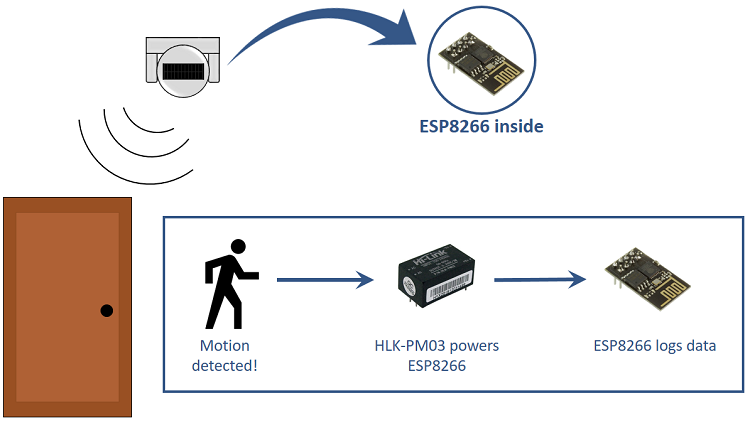
The diagram below provides a high-level overview of the project we will construct.
Motion Sensor
We will modify a commercial motion sensor, ensuring it has sufficient space to accommodate an ESP-01 and the HLK-PM03 AC/DC converter module. Our motion sensor was purchased for $5 from a local store.
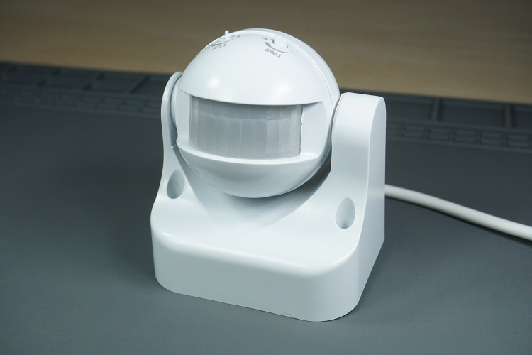
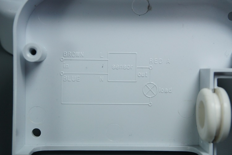
When the PIR sensor detects motion, power is supplied through the red hot wire, capable of activating a lamp or device. Your motion sensor should include a wiring diagram on the lid or in the instruction manual.
In our setup, the output load of the motion sensor is the HLK-PM03 AC/DC converter module, which powers the ESP8266.

The HLK-PM03 module’s AC/DC converter provides 3.3V from either 110VAC or 220VAC, making it ideal for powering the ESP8266 from mains voltage.
You may need to adjust the sensor’s duration of activity to ensure the ESP8266 has sufficient time to execute its tasks. The sensor should have knobs for adjusting both time and luminosity.

In our example, upon powering up, the ESP8266 runs a sketch that sends information to Node-RED via MQTT to log the date and time of motion detection.
Alternatively, instead of sending information to Node-RED, you can perform other tasks such as:
- Logging data to a Google Spreadsheet
- Sending an email alert for motion detection
- Sending notifications to your smartphone
These tasks can be easily accomplished using IFTTT.
#1. Building the Circuit
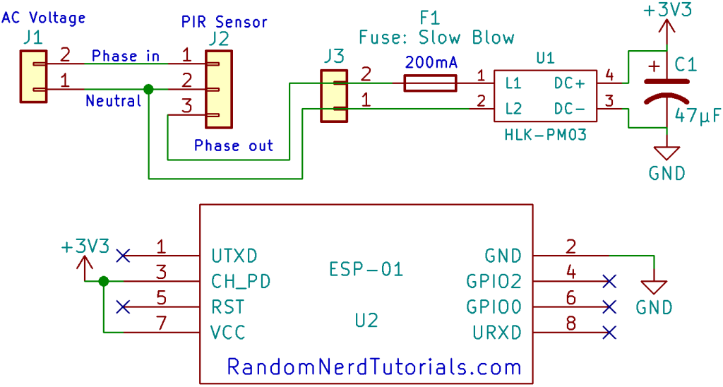
The schematic diagram below illustrates the circuit for this project.
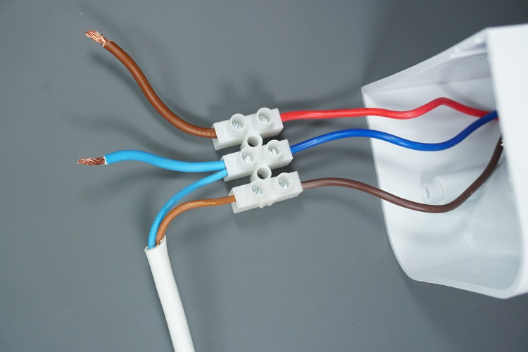
Start by removing the lid of your PIR motion sensor. Inside, you should find three wires: phase in, neutral, and phase out. Follow these steps:
- Connect phase in (brown) and neutral (blue) wires to the motion sensor.
- Connect neutral (blue) and phase out (red) wires to the input of the HLK-PM03.
It’s advisable to incorporate a slow-blow fuse just before the HKL-PM03 converter and a capacitor at the output.
The HLK-PM03 supplies 3.3V and GND, which are linked to the ESP8266’s VCC and GND pins to provide power.
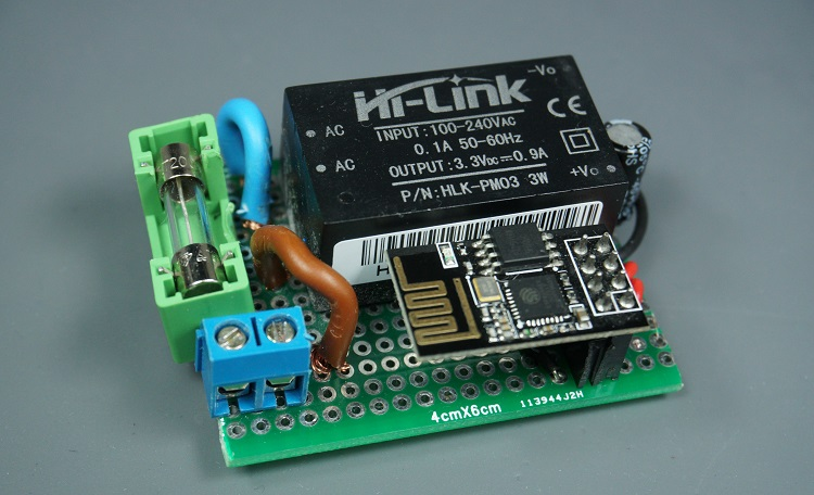
We’ve assembled the HLK-PM03 and ESP8266 circuit on a compact protoboard to conserve space. Additionally, we’ve included header pins for the ESP8266-01 module, allowing for easy attachment and detachment of the board whenever new code needs to be uploaded.
#2. Writing and Uploading the ESP8266 Code
To program the ESP8266, we’ll utilize the Arduino IDE. Before uploading any code to your ESP8266, ensure you have installed the ESP8266 add-on (Install the ESP8266 Board in Arduino IDE) if you haven’t already done so.
Additionally, you’ll need to install the PubSubClient library to establish an MQTT client with the ESP8266. This library facilitates simple publish/subscribe messaging with a server supporting MQTT, essentially enabling communication between your ESP8266 and Node-RED.
Follow these steps:
- Download the PubSubClient library by clicking here. This will result in a .zip folder in your Downloads directory.
- Unzip the .zip folder to obtain the pubsubclient-master folder.
- Rename the folder from pubsubclient-master to pubsubclient.
- Move the pubsubclient folder to the libraries folder within your Arduino IDE installation directory.
Next, copy the provided code to your Arduino IDE, but refrain from uploading it immediately. You’ll need to make several modifications to tailor it to your specific requirements.
Ensure to edit the code with your own SSID, password, and MQTT Broker IP Address (Raspberry Pi IP Address).
#include <ESP8266WiFi.h>
#include <PubSubClient.h>

// Replace with your SSID, password and MQTT broker IP address
const char* ssid = "REPLACE_WITH_YOUR_SSID";
const char* password = "REPLACE_WITH_YOUR_PASSWORD";
const char* mqtt_server = "REPLACE_WITH_YOUR_MQTT_BROKER_IP";
//For example
//const char* mqtt_server = "192.168.1.144";

WiFiClient espClient;
PubSubClient client(espClient);

void setup_wifi() {

  delay(10);
  // We start by connecting to a WiFi network
  Serial.println();
  Serial.print("Connecting to ");
  Serial.println(ssid);

  WiFi.begin(ssid, password);

  while (WiFi.status() != WL_CONNECTED) {
    delay(500);
    Serial.print(".");
  }

  randomSeed(micros());

  Serial.println("");
  Serial.println("WiFi connected");
  Serial.println("IP address: ");
  Serial.println(WiFi.localIP());
}

void reconnect() {
  // Loop until we're reconnected
  while (!client.connected()) {
    Serial.print("Attempting MQTT connection...");
    // Create a random client ID
    String clientId = "ESP8266Client-";
    clientId += String(random(0xffff), HEX);
    // Attempt to connect
    if (client.connect(clientId.c_str())) {
      Serial.println("connected");
    } else {
      Serial.print("failed, rc=");
      Serial.print(client.state());
      Serial.println(" try again in 5 seconds");
      // Wait 5 seconds before retrying
      delay(5000);
    }
  }
}

void setup() {
  pinMode(BUILTIN_LED, OUTPUT);     // Initialize the BUILTIN_LED pin as an output
  digitalWrite(BUILTIN_LED, HIGH);
  Serial.begin(115200);
  setup_wifi();
  client.setServer(mqtt_server, 1883);
  while (!client.connected()) {
    reconnect();
  }
  Serial.print("Motion Detected");
  // Publish MQTT message
  String mqttMessage = "Motion Detected";
  client.publish("esp/pir", mqttMessage.c_str());
}

void loop() {
  client.loop();
}
Include your network credentials
You need to include your network credentials in the following lines.
const char* ssid = "REPLACE_WITH_YOUR_SSID";
const char* password = "REPLACE_WITH_YOUR_PASSWORD";
Include your MQTT broker IP address
You also need to include your MQTT broker IP address.
const char* mqtt_server = "REPLACE_WITH_YOUR_MQTT_BROKER_IP";
To find your MQTT broker IP address, it should be configured first. We’re using Mosquitto broker hosted on a Raspberry Pi. Follow the next resources if you haven’t done that yet:
- How to Install Mosquitto Broker on Raspberry Pi
- Testing Mosquitto Broker and Client on Raspbbery Pi
Code Explanation
The code functions quite straightforwardly. It essentially publishes a message on a specific topic. Additionally, for testing purposes, we activate the on-board LED each time the ESP8266 is powered. This setup is executed within the setup() function because it runs only once, when motion is detected and while the ESP8266 is powered.
void setup() {
   pinMode(BUILTIN_LED, OUTPUT); // BUILTIN_LED pin as an output
   digitalWrite(BUILTIN_LED, HIGH);
   Serial.begin(115200);
   setup_wifi();
   client.setServer(mqtt_server, 1883);
   while (!client.connected()) {
     reconnect();
   }
   Serial.print("Motion Detected");
   // Publish MQTT message
   String mqttMessage = "Motion Detected";
   client.publish("esp/pir", mqttMessage.c_str());
}
Uploading the code
Once you’ve customized the code with your network credentials, you can proceed to upload it to your board. To upload the code to the ESP8266-01, you’ll need a serial adapter or an FTDI programmer.
#3. Creating the Node-RED Flow
Before you start creating the flow, ensure that the following are installed on your Raspberry Pi:
- Node-RED
- Node-RED Dashboard
- Mosquitto Broker
Importing the Node-RED Flow
To import the provided Node-RED flow, follow these steps:
Visit the GitHub repository or click the figure below to view the raw file, then copy the provided code.

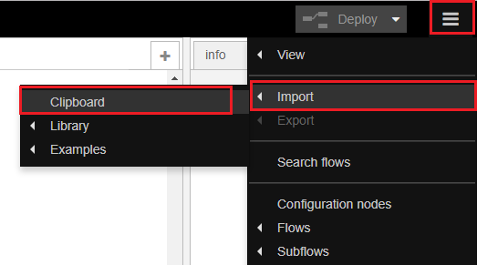
In the Node-RED window, located at the top right corner, select the menu and navigate to Import > Clipboard.
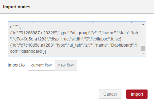
Paste the copied code and click Import.
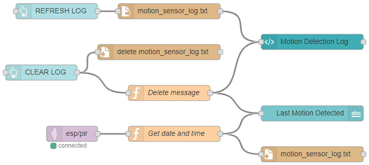
Once imported, you’ll see the flow. It’s designed to receive MQTT messages from the ESP8266 and log the time whenever motion is detected. Additionally, two buttons are included for clearing and refreshing the log.
Node-RED Dashboard
After making all necessary adjustments, click the Deploy button to save your changes.

Your Node-RED application is now ready. To access the Node-RED Dashboard and view your application, open any browser within your local network and enter the following address:
Demonstration
Now, you can test your project. Whenever motion is detected, the ESP8266 powers up and sends a message via MQTT to Node-RED.
By accessing your Node-RED Dashboard, you can observe all the logs detailing when motion was detected. Your application should resemble the figure below.
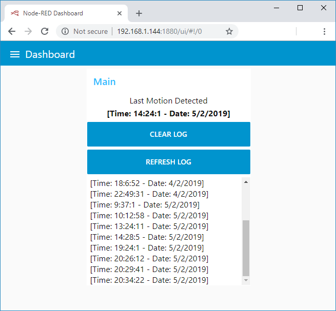
The dashboard displays the most recent instance of motion detection along with all previous logs. Additionally, you have the option to refresh the log or clear it. Please note that clearing the log is irreversible.
Wrapping Up
This project demonstrated how to enhance a commercial motion sensor with an ESP8266 to add intelligence to it. You can easily power the ESP8266 with the HLK-PM03 from mains voltage, creating a compact circuit that fits within the motion sensor.
Upon motion detection, the ESP8266 is powered and performs a task. In this instance, it publishes an MQTT message to log the time of motion detection, but you can customize the code to execute any desired task.
We hope you’ve found this project helpful. If you enjoyed this project, you may also be interested in the following resources:
- Mastering ESP8266 GPIO Interrupts: Arduino IDE Configuration Tips
- Complete ESP8266 Pinout Reference: Simplify Your Hardware Connections
- Beginner’s Guide: ESP8266 NodeMCU Digital Input and Output Setup
- Arduino IDE Tutorial: ESP8266 NodeMCU PWM for LED Dimming (Analog Output)
- NodeMCU Deep Sleep: Enhancing ESP8266 Power Efficiency


