
This beginner’s guide will teach you how to interpret digital signals from components such as button switches and manage digital signals to control components like LEDs using the ESP32 with Arduino IDE.
ESP32 Control Digital Outputs
To begin, designate the GPIO you wish to manage as an OUTPUT. Utilize the pinMode() function in the following manner:
pinMode(GPIO, OUTPUT);
For digital output control, simply employ the digitalWrite() function. This function requires the GPIO (as an integer) you are targeting and the desired state, either HIGH or LOW.
digitalWrite(GPIO, STATE);
Note that all GPIOs, with the exception of GPIOs 6 to 11 (linked to the integrated SPI flash) and GPIOs 34, 35, 36, and 39 (solely input GPIOs), can serve as outputs.
ESP32 Read Digital Inputs
To start, designate the GPIO you wish to read as an INPUT using the pinMode() function in the following manner:
pinMode(GPIO, INPUT);
To interpret a digital input, such as from a button, employ the digitalRead() function. This function requires the GPIO (as an integer) you are addressing.
digitalRead(GPIO);
All GPIOs on the ESP32 can function as inputs, except GPIOs 6 to 11, which are linked to the integrated SPI flash.
Project Example
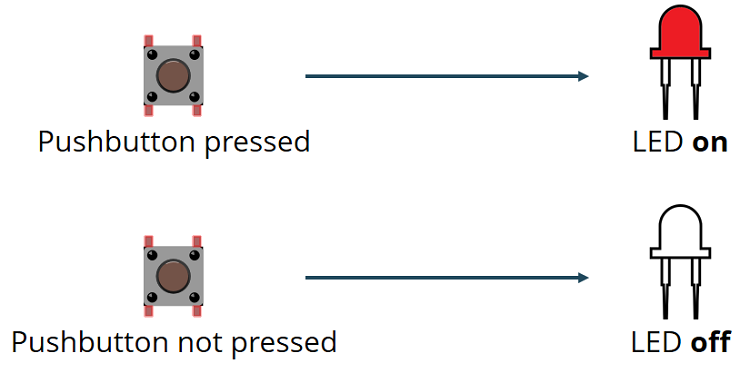
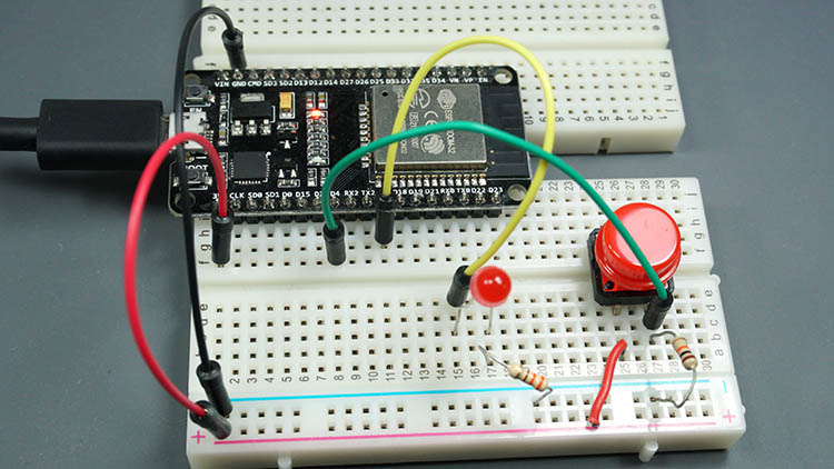
To demonstrate the utilization of digital inputs and outputs, we’ll construct a basic project featuring a pushbutton and an LED. We’ll monitor the pushbutton’s state and illuminate the LED correspondingly, as depicted in the diagram below.
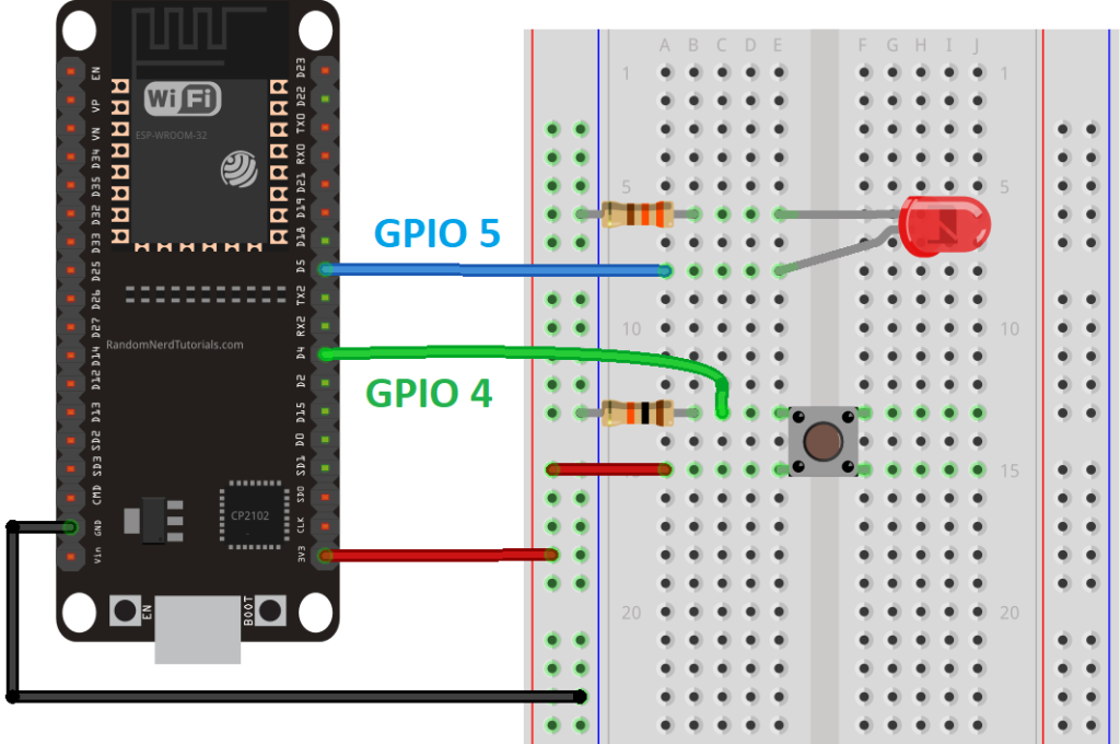
Schematic Diagram
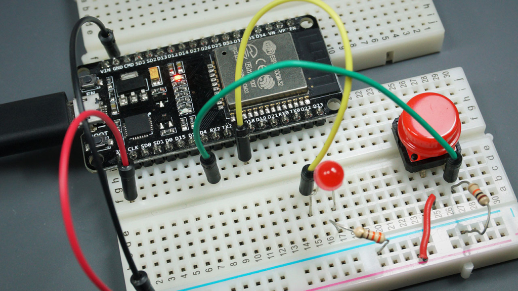
Before moving forward, assemble a circuit comprising an LED and a pushbutton. Connect the LED to GPIO 5 and the pushbutton to GPIO 4.
Parts Required
| Component Name | Buy Now |
| ESP32-WROOM-32 Development | Amazon |
Code
Paste the following code into your Arduino IDE.
// set pin numbers
const int buttonPin = 4;  // the number of the pushbutton pin
const int ledPin =  5;    // the number of the LED pin

// variable for storing the pushbutton status
int buttonState = 0;

void setup() {
  Serial.begin(115200);
  // initialize the pushbutton pin as an input
  pinMode(buttonPin, INPUT);
  // initialize the LED pin as an output
  pinMode(ledPin, OUTPUT);
}

void loop() {
  // read the state of the pushbutton value
  buttonState = digitalRead(buttonPin);
  Serial.println(buttonState);
  // check if the pushbutton is pressed.
  // if it is, the buttonState is HIGH
  if (buttonState == HIGH) {
    // turn LED on
    digitalWrite(ledPin, HIGH);
  } else {
    // turn LED off
    digitalWrite(ledPin, LOW);
  }
}
Code Explanation
The first two lines define variables to assign pins:
const int buttonPin = 4;
const int ledPin = 5;
In this setup, the button is connected to GPIO 4, and the LED is connected to GPIO 5. These correspondences are standard when using the Arduino IDE with the ESP32.
The next line creates a variable to hold the button state. By default, it’s set to 0, indicating the button is not pressed:
int buttonState = 0;
In the setup() function, the button is initialized as an INPUT, and the LED is initialized as an OUTPUT using pinMode():
pinMode(buttonPin, INPUT);
pinMode(ledPin, OUTPUT);
In the loop(), the code reads the button state and adjusts the LED accordingly. First, the button state is read and stored in the buttonState variable using digitalRead():
buttonState = digitalRead(buttonPin);
Then, an if statement checks if the button state is HIGH. If it is, it turns the LED on using digitalWrite():
if (buttonState == HIGH) {
  digitalWrite(ledPin, HIGH);
}
If the button state is not HIGH, it sets the LED off by writing LOW to the LED pin:
else {
  digitalWrite(ledPin, LOW);
}
Uploading the Code
Before initiating the upload process, navigate to Tools > Board, and select the board you’re utilizing. In my instance, it’s the DOIT ESP32 DEVKIT V1 board.
Proceed to Tools > Port and pick the COM port to which the ESP32 is connected. Then, click the upload button and await the “Done uploading” confirmation message.

Testing the Circuit
Post uploading the code, evaluate your circuit. The LED should illuminate upon pressing the pushbutton:
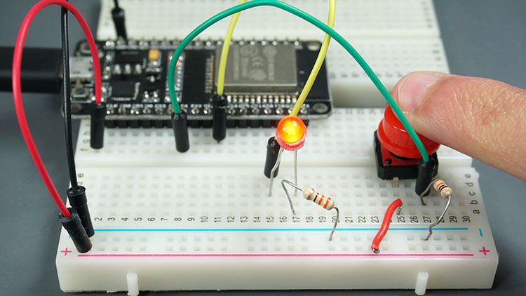
And extinguish upon release:
Wrapping Up
Through this beginner’s guide, you’ve acquired the skills to interpret digital inputs and manage digital outputs with the ESP32 using Arduino IDE.
Should you wish to delve into reading analog inputs or generating PWM signals, refer to the subsequent guides:
- Exploring ESP32 PWM: Your Complete Starter’s Guide to PWM Signals
- Essential ESP32 ADC Basics: Analog-to-Digital Converter Explained


