

This manual demonstrates the utilization of the HC-SR04 Ultrasonic Sensor alongside the ESP8266 NodeMCU board, employing the Arduino core. Employing sonar, the ultrasonic sensor gauges the distance to an object. Instructions for wiring the sensor to the ESP8266 ultrasonic sensor will be provided, along with various example sketches illustrating how to ascertain the distance to an object using the HC-SR04.
Presenting the HC-SR04 Ultrasonic Sensor.
Utilizing sonar technology, the HC-SR04 ultrasonic sensor calculates the distance to an object. This sensor is capable of reading distances ranging from 2cm to 400cm (0.8inch to 157inch) with an accuracy of 0.3cm (0.1inches), making it suitable for a wide array of hobbyist projects. Furthermore, this module includes ultrasonic transmitter and receiver components.
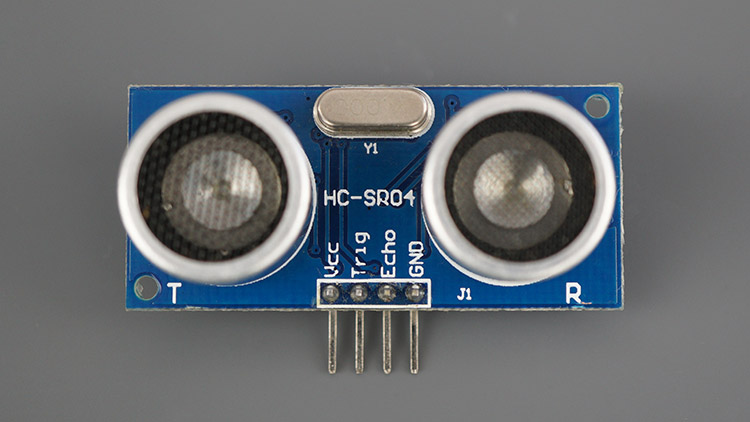
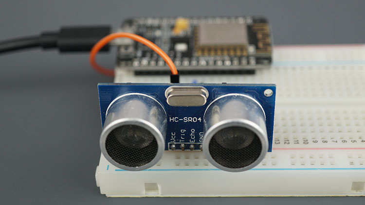
The image below displays the HC-SR04 ultrasonic sensor.
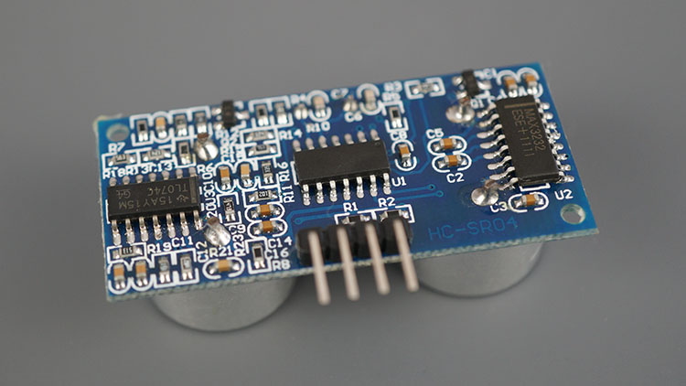
The subsequent image illustrates the reverse side of the sensor.
Technical Specifications of the HC-SR04 Ultrasonic Sensor
Displayed below is a table containing the primary features and specifications of the HC-SR04 ultrasonic sensor esp8266. For further details, please refer to the sensor’s datasheet.
| Power Supply | 5V DC |
| Working Current | 15 mA |
| Working Frequency | 40 kHz |
| Maximum Range | 4 meters |
| Minimum Range | 2 cm |
| Measuring Angle | 15º |
| Resolution | 0.3 cm |
| Trigger Input Signal | 10uS TTL pulse |
| Echo Output Signal | TTL pulse proportional to the distance range |
| Dimensions | 45mm x 20mm x 15mm |
HC-SR04 Ultrasonic Sensor Pinout
Here’s the pinout of the HC-SR04 Ultrasonic Sensor.
| VCC | Powers the sensor (5V) |
| Trig | Trigger Input Pin |
| Echo | Echo Output Pin |
| GND | Common GND |
How Does the HC-SR04 Ultrasonic Sensor Operate?
The ultrasonic sensor esp8266 employs sonar principles to ascertain the distance to an object. Here’s a breakdown of its functioning:
- The ultrasound transmitter, triggered by the trig pin, emits a high-frequency sound at 40 kHz.
- This sound propagates through the air. Upon encountering an object, it reflects back toward the sensor module.
- The ultrasound receiver, connected to the echo pin, picks up the reflected sound, or echo.
- By considering the speed of sound in the air and the time taken for the sound to travel (the duration between signal transmission and reception), we can compute the distance to the object. The formula is as follows:
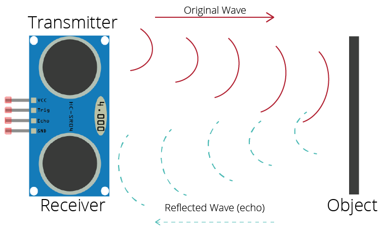
distance to an object = ((speed of sound in the air)*time)/2
- speed of sound in the air at 20ºC (68ºF) = 343m/s
Schematic – ESP8266 NodeMCU with HC-SR04 Ultrasonic Sensor
Connect the HC-SR04 ultrasonic sensor to the ESP8266 ultrasonic sensor according to the schematic diagram below. In this configuration, we’re linking the Trig pin to GPIO 5 and the Echo pin to GPIO 18, though alternative pins can be utilized if preferred.
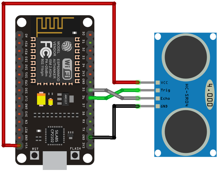
| Ultrasonic Sensor | ESP8266 |
| VCC | VIN |
| Trig | GPIO 12 (D6) |
| Echo | GPIO 14 (D5) |
| GND | GND |
Setting Up Arduino IDE
To program the ESP8266 board, we’ll utilize the Arduino IDE. Ensure that you have installed the ESP8266 add-on. Refer to the following tutorial for guidance:
If you prefer to use VS Code with the PlatformIO extension, opt for the subsequent tutorial instead, which details how to program the ESP8266.
Code – Obtaining Object Distance with HC-SR04 Ultrasonic Sensor and ESP8266
The subsequent sketch demonstrates a straightforward example of how to acquire the distance between the sensor and an object using the ESP8266 board with the Arduino core.
const int trigPin = 12;
const int echoPin = 14;

//define sound velocity in cm/uS
#define SOUND_VELOCITY 0.034
#define CM_TO_INCH 0.393701

long duration;
float distanceCm;
float distanceInch;

void setup() {
  Serial.begin(115200); // Starts the serial communication
  pinMode(trigPin, OUTPUT); // Sets the trigPin as an Output
  pinMode(echoPin, INPUT); // Sets the echoPin as an Input
}

void loop() {
  // Clears the trigPin
  digitalWrite(trigPin, LOW);
  delayMicroseconds(2);
  // Sets the trigPin on HIGH state for 10 micro seconds
  digitalWrite(trigPin, HIGH);
  delayMicroseconds(10);
  digitalWrite(trigPin, LOW);

  // Reads the echoPin, returns the sound wave travel time in microseconds
  duration = pulseIn(echoPin, HIGH);

  // Calculate the distance
  distanceCm = duration * SOUND_VELOCITY/2;

  // Convert to inches
  distanceInch = distanceCm * CM_TO_INCH;

  // Prints the distance on the Serial Monitor
  Serial.print("Distance (cm): ");
  Serial.println(distanceCm);
  Serial.print("Distance (inch): ");
  Serial.println(distanceInch);

  delay(1000);
}
Upload the code to your board, and it will function immediately. Keep reading if you wish to understand how the code operates or skip to the demonstration section.
How the Code Functions
Firstly, define the trigger and echo pins:
const int trigPin = 12;
const int echoPin = 14;
In this instance, GPIO 12 and GPIO 14 are used. However, alternate GPIOs can be employed—refer to the ESP8266 Pinout Reference: Which GPIO pins should you use?
The SOUND_VELOCITY variable stores the velocity of sound in air at 20°C, expressed in cm/uS.
#define SOUND_SPEED 0.034
The CM_TO_INCH variable facilitates the conversion of distance from centimeters to inches.
#define CM_TO_INCH 0.393701
Next, initialize the following variables:
long duration;
float distanceCm;
float distanceInch;
The duration variable records the travel time of the ultrasonic waves (elapsed time between transmission and reception of the pulse wave). distanceCm and distanceInch, as their names suggest, store the distance to an object in centimeters and inches, respectively.
setup()
In the setup(), commence serial communication at a baud rate of 115200 to enable printing measurements on the Serial Monitor.
Serial.begin(115200); // Starts the serial communication
Define the trigger pin as an OUTPUT—the trigger pin emits ultrasound—and the echo pin as an INPUT—the echo pin receives the reflected wave and sends a proportional signal to the ESP8266 ultrasonic sensor.
pinMode(trigPin, OUTPUT); // Sets the trigPin as an Output
pinMode(echoPin, INPUT); // Sets the echoPin as an Input
loop()
In the loop(), the subsequent lines generate a 10μs HIGH pulse on the trigger pin, signifying emission of ultrasound. Note the short LOW pulse preceding to ensure a clean HIGH pulse.
// Clears the trigPin
digitalWrite(trigPin, LOW);
delayMicroseconds(2);
// Sets the trigPin on HIGH state for 10 micro seconds
digitalWrite(trigPin, HIGH);
delayMicroseconds(10);
digitalWrite(trigPin, LOW);
The pulseIn() function is employed to obtain the sound wave travel time:
duration = pulseIn(echoPin, HIGH);
This function reads a HIGH or LOW pulse on a pin, with arguments specifying the pin and pulse state (HIGH or LOW). It returns the pulse length in microseconds, corresponding to the time taken to travel to the object and back.
Subsequently, the distance to an object is calculated, considering the speed of sound:
distanceCm = duration * SOUND_SPEED/2;
Conversion to inches follows:
distanceInch = distanceCm * CM_TO_INCH;
Finally, results are printed on the Serial Monitor:
Serial.print("Distance (cm): ");
Serial.println(distanceCm);
Serial.print("Distance (inch): ");
Serial.println(distanceInch);
Demonstration
Transfer the code to your board. Remember to choose the appropriate board in Tools > Boards. Also, ensure the correct COM port is selected in Tools > Port.
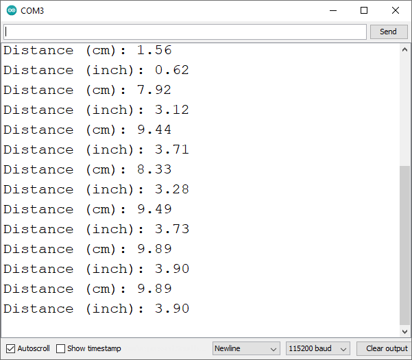
Once uploaded, launch the Serial Monitor at a baud rate of 115200. Press the on-board RST button to restart the board, and it will commence displaying the distance to the nearest object on the Serial Monitor, resembling the illustration below.
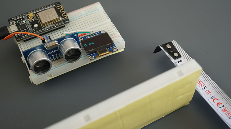
ESP8266 with HC-SR04 and OLED Display
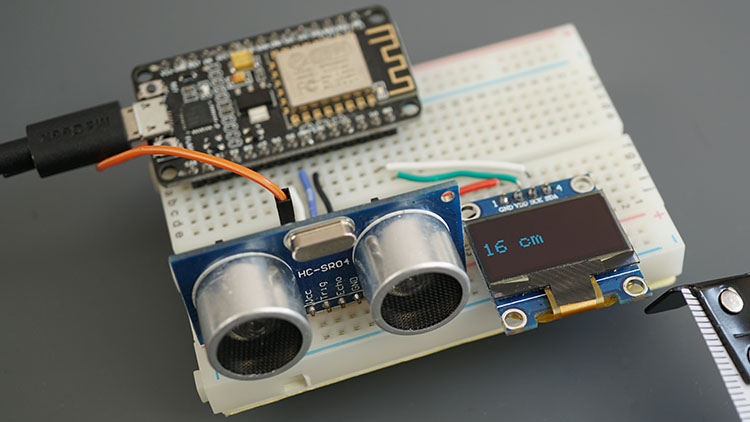
In this segment, we’ll present a straightforward example utilizing the ESP8266, displaying distance readings on an I2C OLED display.
For a deeper understanding of the project’s functionality, we suggest reviewing our ESP8266 tutorial featuring the I2C OLED display.
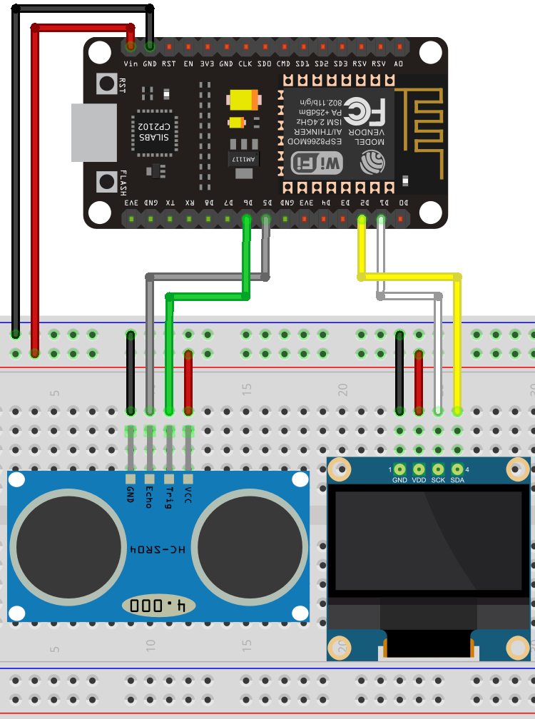
Schematic Diagram – ESP8266 with HC-SR04 and OLED Display
Connect all components according to the schematic diagram provided below.
Code – Displaying Distance (HC-SR04) on OLED with ESP8266
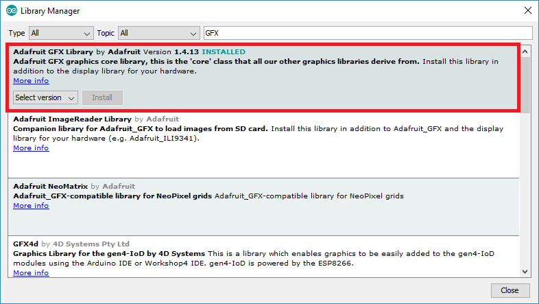
Before utilizing this example, ensure you have installed the Adafruit SSD1306 and Adafruit GFX libraries. You can install these libraries via the Arduino Library Manager.
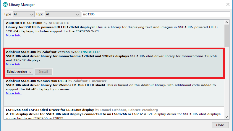
Navigate to Sketch > Library > Manage Libraries, search for “SSD1306,” and install the SSD1306 library from Adafruit. Once the SSD1306 library is installed, search for “GFX” in the search box and install the library.
After installing the libraries, restart your Arduino IDE.
Next, simply copy the following code to your Arduino IDE and upload it to the board.
#include <Wire.h>
#include <Adafruit_GFX.h>
#include <Adafruit_SSD1306.h>

#define SCREEN_WIDTH 128 // OLED display width, in pixels
#define SCREEN_HEIGHT 64 // OLED display height, in pixels

// Declaration for an SSD1306 display connected to I2C (SDA, SCL pins)
Adafruit_SSD1306 display(SCREEN_WIDTH, SCREEN_HEIGHT, &Wire, -1);

const int trigPin = 12;
const int echoPin = 14;

//define sound speed in cm/uS
#define SOUND_SPEED 0.034
#define CM_TO_INCH 0.393701

long duration;
int distanceCm;
int distanceInch;

void setup() {
  Serial.begin(115200);
  pinMode(trigPin, OUTPUT); // Sets the trigPin as an Output
  pinMode(echoPin, INPUT); // Sets the echoPin as an Input

  if(!display.begin(SSD1306_SWITCHCAPVCC, 0x3C)) {
    Serial.println(F("SSD1306 allocation failed"));
    for(;;);
  }
  delay(500);
  display.clearDisplay();

  display.setTextSize(2);
  display.setTextColor(WHITE);
}

void loop() {
  // Clears the trigPin
  digitalWrite(trigPin, LOW);
  delayMicroseconds(2);
  // Sets the trigPin on HIGH state for 10 micro seconds
  digitalWrite(trigPin, HIGH);
  delayMicroseconds(10);
  digitalWrite(trigPin, LOW);

  // Reads the echoPin, returns the sound wave travel time in microseconds
  duration = pulseIn(echoPin, HIGH);

  // Calculate the distance
  distanceCm = duration * SOUND_SPEED/2;

  // Convert to inches
  distanceInch = distanceCm * CM_TO_INCH;

  // Prints the distance in the Serial Monitor
  Serial.print("Distance (cm): ");
  Serial.println(distanceCm);
  Serial.print("Distance (inch): ");
  Serial.println(distanceInch);

  display.clearDisplay();
  display.setCursor(0, 25);
  // Display distance in cm
  display.print(distanceCm);
  display.print(" cm");

  // Display distance in inches
  /*display.print(distanceInch);
  display.print(" in");*/
  display.display();

  delay(500);
}
How the Code Works
Commence by including the necessary libraries for the OLED display:
#include <Wire.h>
#include <Adafruit_GFX.h>
#include <Adafruit_SSD1306.h>
Define the width and height of the OLED display. Here, we’re utilizing a 128×64 OLED display:
#define SCREEN_WIDTH 128 // OLED display width, in pixels
#define SCREEN_HEIGHT 64 // OLED display height, in pixels
Create an Adafruit_SSD1306 object named display to manage the OLED display:
Adafruit_SSD1306 display = Adafruit_SSD1306(128, 64, &Wire);
Define the pins to which the HC-SR04 sensor is connected:
const int trigPin = 12;
const int echoPin = 14;
Establish variables to store the distance and the duration between the transmission and reception of the sound waves:
long duration;
int distanceCm;
int distanceInch;
setup()
In the setup(), initiate serial communication at a baud rate of 115200 to print results on the Serial Monitor:
Serial.begin(115200);
Define the trigger pin as an OUTPUT and the echo pin as an INPUT:
pinMode(trigPin, OUTPUT); // Sets the trigPin as an Output
pinMode(echoPin, INPUT); // Sets the echoPin as an Input
Initialize the OLED display:
if(!display.begin(SSD1306_SWITCHCAPVCC, 0x3C)) {
  Serial.println(F("SSD1306 allocation failed"));
  for(;;);
}
Set the font size and color for the display.
display.setTextSize(2);
display.setTextColor(WHITE);
loop()
Within the loop(), we acquire the distance and display it on the OLED.
Retrieve the distance (as explained in the previous section on distance calculation).
Print the distance on the Serial Monitor:
// Clears the trigPin
digitalWrite(trigPin, LOW);
delayMicroseconds(2);
// Sets the trigPin on HIGH state for 10 micro seconds
digitalWrite(trigPin, HIGH);
delayMicroseconds(10);
digitalWrite(trigPin, LOW);

// Reads the echoPin, returns the sound wave travel time in microseconds
duration = pulseIn(echoPin, HIGH);

// Calculate the distance
distanceCm = duration * SOUND_SPEED/2;

// Convert to inches
distanceInch = distanceCm * CM_TO_INCH;
Print the distance on the Serial Monitor.
// Prints the distance on the Serial Monitor
Serial.print("Distance (cm): ");
Serial.println(distanceCm);
Serial.print("Distance (inch): ");
Serial.println(distanceInch);
Clear the display in each loop() to write new readings.
display.clearDisplay();
Set the display cursor to (0, 25).
display.setCursor(0, 25);
The following lines print the distance in centimeters in the OLED display.
// Display static text
display.print(distanceCm);
display.print(" cm");
Comment the previous lines and uncomment the following lines if you want to display the readings in inches.
/* Display distance in inches
display.print(distanceInch);
display.print(" in");*/
Lastly, call display.display() to actually show the readings on the OLED.
display.display();
The distance is updated every 500 milliseconds.
delay(500);
Demonstration
Navigate to Tools > Board and select the ESP8266 ultrasonic sensor board you are utilizing. Then, go to Tools > Port and choose the port your board is connected to. Finally, click the upload button.
Launch the Serial Monitor at a baud rate of 115200, and press the on-board RST button. The sensor measurements will be exhibited both on the Serial Monitor and on the OLED display.
Position an object in front of the sensor and observe the values fluctuating.
Wrapping Up
The HC-SR04 Ultrasonic Sensor enables the determination of distance to an object. In this tutorial, you have gained insights into utilizing the HC-SR04 with the ESP8266. For additional tutorials on other popular sensors, feel free to explore our resources.
- Master DC Motor Control: ESP8266 NodeMCU and L298N Driver Tutorial
- DIY Water Quality Testing: ESP8266 NodeMCU and TDS Sensor
- Step-by-Step Guide: ESP8266 NodeMCU + Stepper Motor (28BYJ-48) Setup
- ESP8266 NodeMCU: MAX6675 Amplifier for Precise Thermocouple Readings


