
In your upcoming project, you may need to utilize your Arduino to control devices that operate at high voltages, such as lamps, fans, or household appliances. However, since Arduino operates at 5 volts, it cannot directly interface with these high-voltage devices.
To bridge this gap, relay modules prove to be useful. These modules are compact, affordable, and easy to connect, making them ideal for DIY projects that involve switching moderate amounts of AC or DC power. It’s worth noting that, being electro-mechanical devices, relays may experience wear and tear over time.
This tutorial will guide you through the process of setting up a relay module to control the activation of a lamp or other devices. But before we proceed, let’s provide a brief overview of relays.
How Do Relays Work?
At the heart of a relay is an electromagnet, which is essentially a wire coil that becomes temporarily magnetized when an electric current passes through it. Think of a relay as an electrical lever: it is activated by a small current and, in turn, controls the flow of a much larger current to another device.
Relay Basics
Let’s visualize how a relay connects two circuits using a simple animation.
Imagine two circuits: one consists of an electromagnet and a switch or sensor, while the other includes a magnetic switch and a light bulb.
Initially, both circuits are open, meaning no current is flowing through them.
When a small current is applied to the first circuit, the electromagnet becomes energized, generating a magnetic field around it. This magnetic field attracts the contact in the second circuit, closing the switch and allowing a larger current to flow.
Once the current in the first circuit ceases, the contact returns to its original position, opening the switch in the second circuit.
Relay Operation
A typical relay has five pins, three of which are high voltage terminals: NC (normally closed), COM (common), and NO (normally open). These pins are connected to the device being controlled.
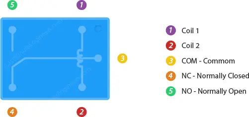
The controlled device is connected between the COM terminal and either the NC or NO terminal, depending on whether it should remain normally on or off.
The remaining two pins, coil1 and coil2, are part of a coil that acts as an electromagnet.
By default, the COM terminal is connected to the NC terminal, and the NO terminal is open.
When current flows through the coil, the electromagnet becomes energized, causing the internal contact of the switch to move. This action connects the COM terminal to the NO terminal, breaking the connection with the NC terminal.
When the current stops flowing through the coil, the internal contact returns to its initial position, reconnecting the NC terminal to the COM terminal and reopening the NO terminal.
In essence, a relay operates as a single-pole-double-throw switch (SPDT).
One-Channel Relay Module Hardware Overview
The one-channel relay module is specifically designed to enable your Arduino to control a single high-powered device. It features a relay with a maximum current rating of 10A at 250VAC or 30VDC, providing robust control capabilities.
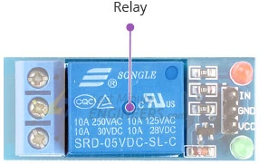
If your project requires additional channels, you can also find relay modules with two, four, or eight channels to suit your specific needs.
LED Indicators
The relay module incorporates two LEDs for visual feedback.
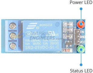
The power LED illuminates when the module is powered on, indicating its operational status. The status LED lights up when the relay is activated, providing a clear indication of its switching state.
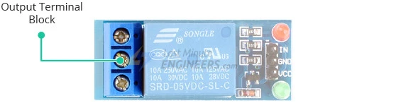
Output Terminal Block
To facilitate easy connections, the relay’s high voltage terminals (NC, COM, and NO) are accessible via a screw terminal on the module. You can conveniently connect the device you intend to control across these terminals.
Control Pin
On the opposite side of the module, you will find an input pin labeled IN, which is responsible for controlling the relay. This input pin is compatible with 5V logic, making it compatible with microcontrollers such as Arduino. By utilizing any digital output pin of your microcontroller, you can effectively drive the relay.
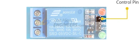
It’s important to note that the input pin operates on an active low basis. This means that providing a logic LOW signal will activate the relay, while a logic HIGH signal will deactivate it.
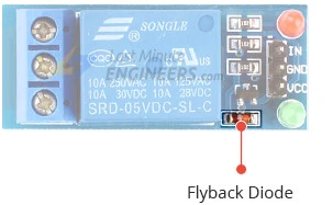
Module Power
The relay module operates on a 5V power supply and consumes approximately 70mA of current when the relay is activated.
Furthermore, the module includes a flyback diode connected in parallel with the relay coil. This diode serves to safely dissipate any back electromotive force generated when the relay coil is de-energized, protecting the module and ensuring proper functionality.
One-Channel Relay Module Pinout
Let’s examine the pinout of the one-channel relay module.
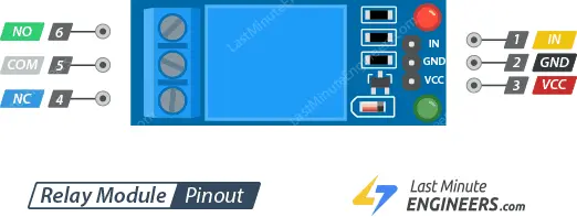
Power Pins:
GND: This pin serves as the common ground connection.
VCC: Connect the power supply to this pin to provide voltage to the module.
Control Pin:
IN: Use this pin to control the relay. It operates on an active low logic, meaning that setting it to LOW activates the relay, while setting it to HIGH deactivates it.
Output Terminals:
COM: This terminal is intended for connecting the device you wish to control.
NC: The NC (Normally Closed) terminal is normally connected to the COM terminal. When the relay is activated, this connection is broken.
NO: The NO (Normally Open) terminal is typically unconnected. However, when the relay is activated, it establishes a connection with the COM terminal.
Wiring a One-Channel Relay Module to an Arduino
Now that we have a good understanding of the relay module, let’s proceed with the wiring to control a lamp.Now that we have a good understanding of the relay module, let’s proceed with the wiring to control a lamp.
The relay module deals with HIGH AC voltage, which can be dangerous if mishandled. Ensure you have the necessary knowledge and experience working with HIGH AC voltage before proceeding.
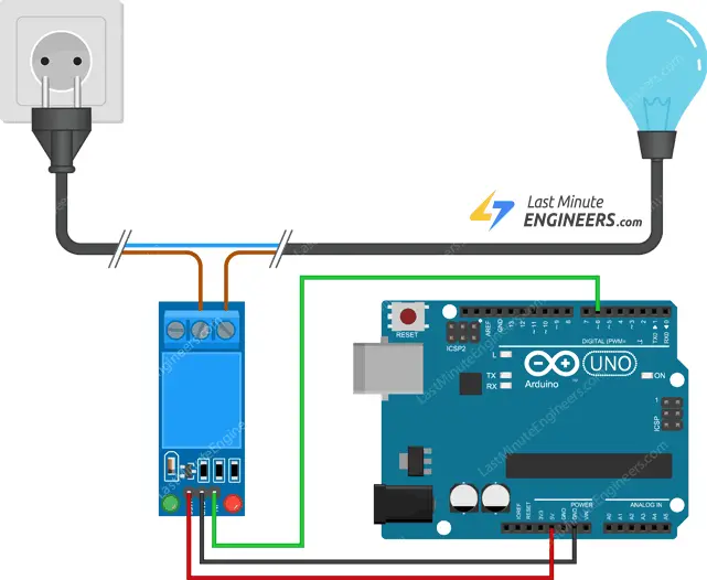
To start, connect the VCC pin of the relay module to the 5V pin on the Arduino, and the GND pin to the ground. Next, connect digital pin #6 on the Arduino to the IN input pin on the relay module.
You will also need to connect the relay module to the AC-powered device you wish to control, such as a lamp. Cut the live AC line and connect one end of the cut wire (coming from the wall) to the COM terminal on the relay module. Connect the other end of the wire to either the NC or NO terminal, depending on the initial state you desire for your device.
If you want the device to remain off most of the time and only turn on when activated, connect the other end of the wire to the NO terminal. If you want the device to be on by default and turn off when activated, connect it to the NC terminal.
For our lamp project, we want the lamp to be off initially and turn on when the relay is activated. Therefore, we will connect one end of the wire to the COM terminal and the other end to the NO terminal.
Refer to the illustration below for a visual representation of the wiring setup.
Parts Required
| Component Name | Buy Now |
| Arduino Uno REV3 | Amazon |
| 5V One Channel Relay Module | Amazon |
| Breadboard | Amazon |
| BOJACK 1000 Pcs 25 Values Resistor Kit 1 Ohm-1M Ohm with 5% 1/4W | Amazon |
Arduino Example Code
Here’s an example code that demonstrates how to control a relay module using an Arduino. This code will activate the relay for 3 seconds and then deactivate it for 3 seconds.
int RelayPin = 6;

void setup() {
  // Set RelayPin as an output pin
  pinMode(RelayPin, OUTPUT);
}

void loop() {
  // Activate the relay
  digitalWrite(RelayPin, LOW);
  delay(3000);

  // Deactivate the relay
  digitalWrite(RelayPin, HIGH);
  delay(3000);
}
Code Explanation:
The code starts by declaring the variable RelayPin and assigning it the value 6, representing the pin number to which the relay module’s input pin is connected.
int RelayPin = 6;
In the setup() function, the pinMode() function is used to configure the RelayPin as an output pin. This prepares the pin to be used for controlling the relay.
pinMode(RelayPin, OUTPUT);
Inside the loop() function, the relay is activated by calling digitalWrite() with LOW as the second argument, which sets the RelayPin to a logic LOW state. This turns on the relay and allows current to flow through, activating the connected device. The program then pauses for 3 seconds using the delay() function.
digitalWrite(RelayPin, LOW);
delay(3000);

digitalWrite(RelayPin, HIGH);
delay(3000);
Next, the relay is deactivated by calling digitalWrite() with HIGH as the second argument, setting the RelayPin to a logic HIGH state. This turns off the relay, cutting off the current flow and deactivating the connected device. Another 3-second delay is added using delay().
This cycle of activating and deactivating the relay repeats indefinitely in the loop() function, creating a 3-second on-off cycle for the relay and the connected device.
You can adjust the duration of the delays or modify the code to add more complex functionality based on your specific requirements.
Related article
- Step-by-Step Guide: Interface 2 Channel Relay Channels with Arduino
- Remote AC Appliance Control with ESP8266 NodeMCU Relay
- Arduino and MCP2515: Build Your Own CAN Bus Network


