

Controlling stepper motors becomes simple and cost-effective by connecting the L293D Motor Driver IC to an Arduino. This IC enables control over both the speed and spinning direction of various stepper motors, including Unipolar stepper motors like 28BYJ-48 or Bipolar stepper motors like NEMA 17.
If you wish to gain a fundamental understanding of the L293D IC, the tutorial provided below is an invaluable resource. It is highly recommended to read through or at least skim this tutorial before proceeding further.
Controlling a Stepper Motor With an H-Bridge
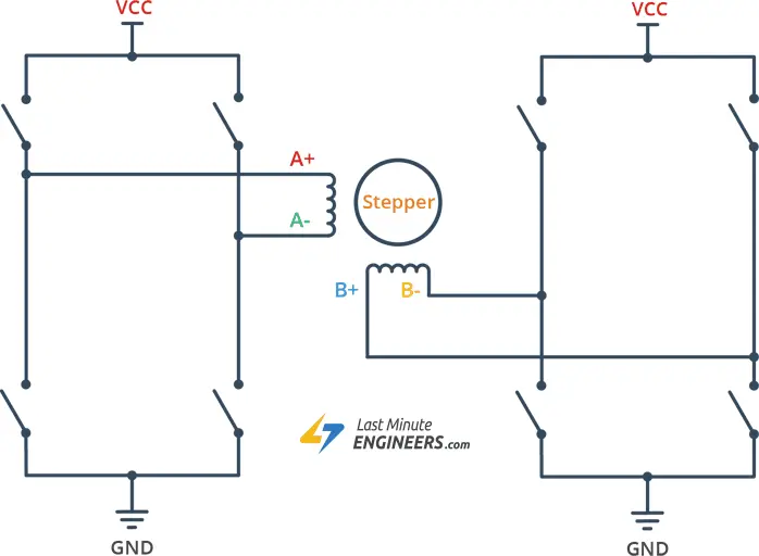
To control a stepper motor using the L293D IC, we utilize its two H-Bridges. Each H-Bridge is responsible for driving one of the electromagnetic coils within the stepper motor.
By energizing these coils in a precise sequence, the stepper motor’s shaft can be moved forward or backward in small, defined steps.
The speed of the motor is influenced by the frequency at which these coils are energized.
The following image illustrates the process of driving a stepper motor using the H-Bridge configuration.
Driving Unipolar Stepper Motor (28BYJ-48)
In this initial experiment, we will be using the 28BYJ-48 unipolar stepper motor, which operates at 5V and provides 48 steps per revolution.
Before connecting the motor to the chip, you must identify the A+, A-, B+, and B- wires on the motor. This information can usually be found in the motor’s datasheet. In our case, the colors for these wires are orange, pink, blue, and yellow.
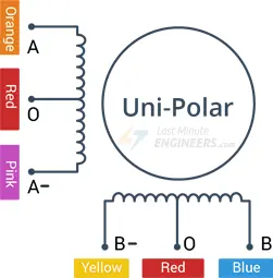
Keep in mind that in this experiment, we won’t be using the common center connection (Red). The center connection is used to energize either the left or right side of the coil, allowing the current flow to be reversed without the need for a circuit that can change the current direction.
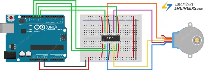
The connections are straightforward. Begin by connecting the 5V output of the Arduino to the Vcc2 and Vcc1 pins of the L293D IC. Also, connect the ground to ground for both the Arduino and the L293D.
Next, connect both the ENA and ENB pins of the L293D IC to the 5V output of the Arduino, ensuring that the motor is always enabled.
Now, connect the input pins (IN1, IN2, IN3, and IN4) of the L293D IC to four digital output pins (12, 11, 10, and 9) on the Arduino.
Finally, connect the stepper motor’s wires: A+ (Orange), A- (Pink), B- (Yellow), and B+ (Blue) to the L293D’s output pins (Out4, Out3, Out2, and Out1) as illustrated below.
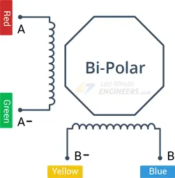
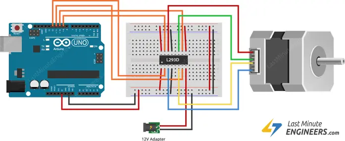
Driving Bipolar Stepper Motor (NEMA 17)
In our next experiment, we will be using the NEMA 17 bipolar stepper motor, which operates at 12V and provides 200 steps per revolution, capable of running at 60 RPM.
Before connecting the motor to the chip, you must identify the A+, A-, B+, and B- wires on the motor. This information can usually be found in the motor’s datasheet. For our motor, these wires are colored red, green, blue, and yellow.
The connections are straightforward. Start by connecting an external 12V power supply to the Vcc2 pin of the L293D IC, and the 5V output of the Arduino to the Vcc1 pin of the IC. Ensure that all the grounds in the circuit are common.
Next, connect both the ENA and ENB pins of the L293D IC to the 5V output of the Arduino, ensuring that the motor is always enabled.
Now, connect the input pins (IN1, IN2, IN3, and IN4) of the L293D IC to four digital output pins (12, 11, 10, and 9) on the Arduino.
Finally, connect the wires A+ (Red), A- (Green), B+ (Blue), and B- (Yellow) from the stepper motor to the L293D’s output pins (Out4, Out3, Out2, and Out1) as illustrated below.
Parts Required
| Component Name | Buy Now |
| Arduino Uno REV3 | Amazon |
| L293 L293D 16-pin IC Stepper Motor Drivers Controllers | Amazon |
| L293D DC Motor Drive Shield Stepper Motor Drive | Amazon |
| Nema 17 Stepper Motor Bipolar 2A 59Ncm(84oz.in) | Amazon |
| Breadboard | Amazon |
| BOJACK 1000 Pcs 25 Values Resistor Kit 1 Ohm-1M Ohm with 5% 1/4W | Amazon |
Arduino Code – Controlling Stepper Motor
The following sketch provides a comprehensive guide on how to control either a unipolar or bipolar stepper motor using the L293D chip. The code is the same for both motors, with the only difference being the parameter stepsPerRevolution.
Before trying out the sketch, make sure to change this parameter according to your motor’s specifications. For example, for the NEMA 17 motor, set it to 200, and for the 28BYJ-48 motor, set it to 48.
// Include the Arduino Stepper Library
#include <Stepper.h>

// Number of steps per output rotation
const int stepsPerRevolution = 200;

// Create Instance of Stepper library
Stepper myStepper(stepsPerRevolution, 12, 11, 10, 9);


void setup()
{
	// set the speed at 20 rpm:
	myStepper.setSpeed(20);
	// initialize the serial port:
	Serial.begin(9600);
}

void loop()
{
	// step one revolution in one direction:
	Serial.println("clockwise");
	myStepper.step(stepsPerRevolution);
	delay(500);

	// step one revolution in the other direction:
	Serial.println("counterclockwise");
	myStepper.step(-stepsPerRevolution);
	delay(500);
}
This line includes the Arduino Stepper Library, which is necessary for controlling the stepper motor.
#include <Stepper.h>
This line creates a constant variable named stepsPerRevolution and sets its value to 200. This value represents the number of steps required for the stepper motor to complete one full revolution. The actual value may vary depending on the stepper motor model.
const int stepsPerRevolution = 200;
Here, an instance of the Stepper class is created, and it is named myStepper. The constructor of the Stepper class is called with the parameters stepsPerRevolution, 12, 11, 10, and 9. These values represent the number of steps per revolution and the Arduino pins connected to the L293D motor driver IC (IN1, IN2, IN3, IN4) that control the stepper motor.
Stepper myStepper(stepsPerRevolution, 12, 11, 10, 9);
In the setup() function, the speed of the stepper motor is set using the setSpeed() method of the myStepper instance. The value 20 represents the speed in revolutions per minute (RPM). The Serial.begin(9600) initializes the serial communication at a baud rate of 9600 for debugging and monitoring.
void setup()
{
	myStepper.setSpeed(20);
	Serial.begin(9600);
}
In the loop() function, the motor rotates one full revolution in the clockwise direction (clockwise), and then it rotates one full revolution in the counterclockwise direction (counterclockwise). This is achieved using the step() method of the myStepper instance. The parameter stepsPerRevolution specifies the number of steps the motor should move. Passing a negative value to myStepper.step() causes the motor to rotate in the opposite direction.
After each rotation, there is a delay(500), which pauses the program for 500 milliseconds before executing the next set of steps. This creates a delay between each rotation for better visualization and monitoring of the motor’s movement.
The code is designed to run in a continuous loop, continuously rotating the stepper motor in one direction and then in the opposite direction, with a delay in between. The serial communication is used to print messages indicating the direction of rotation (“clockwise” and “counterclockwise”) to the serial monitor for observation.
void loop()
{
	// step one revolution in one direction:
	Serial.println("clockwise");
	myStepper.step(stepsPerRevolution);
	delay(500);

	// step one revolution in the other direction:
	Serial.println("counterclockwise");
	myStepper.step(-stepsPerRevolution);
	delay(500);
}


