
What is USART?
USART, which stands for Universal Serial Asynchronous Receiver Transmitter, is a serial communication protocol employed for transmitting and receiving data in a sequential manner at a specified baud rate.
Numerous devices, including GPS, GSM, RFID, sensors, among others, require interaction with a microcontroller for the transmission or reception of information. Various communication protocols such as RS232, SPI, I2C, CAN, are utilized to facilitate communication with the microcontroller. Fundamentally, a protocol constitutes a mutually agreed set of rules between the sender and the receiver, determining:
- How data is structured.
- The number of bits composing a character.
- When data transmission begins and ends.
USART enables the exchange of data with a computer or other devices. It also finds utility in interfacing microcontrollers with diverse modules like Wi-Fi (ESP8266), Bluetooth, GPS, GSM, etc.
Let’s delve into USART-based serial communication.
Asynchronous Communication: Asynchronous operation signifies that a process functions independently of others. Asynchronous communication entails placing each character (data byte) between start and stop bits. The start bit is invariably 0 (low), while the stop bit is invariably 1 (high).
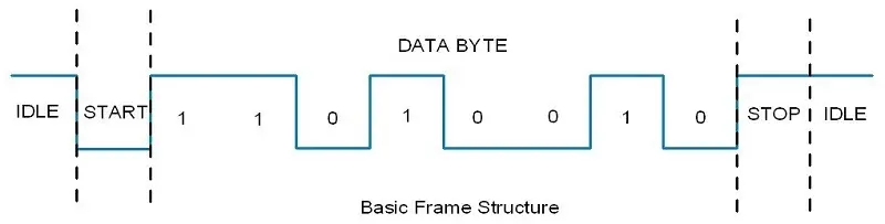
Bit Rate & Baud Rate: The rate of data transfer in serial data communication is denoted in bps (bits per second). Another commonly employed term for bps is baud rate, indicating the number of signal changes per second. As the signal is represented in bits, the bit rate equates to the baud rate.
Parts Required
Arduino USART (Serial Communication)
The Arduino Uno (ATmega328) features a built-in USART, which proves advantageous for serial communication. This functionality facilitates the exchange of data between a PC and various serial devices such as GSM, GPS, Bluetooth, and more.
Arduino establishes communication with serial devices via digital pins 0 (RXD) and 1 (TXD), while communication with a PC or laptop occurs through USB. The USART pins of the Arduino Uno are illustrated in the accompanying image.
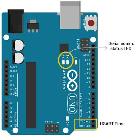
Within the image, two LED indicators, namely TX and RX, are also highlighted. These status LEDs serve to signify the transmission and reception of serial data.
When the PC transmits data serially to the Arduino Uno via USB, the RX LED illuminates to indicate data reception. Conversely, when the Arduino Uno transmits data to the PC via USB, the TX LED illuminates to denote data transmission.
However, the LED status indication operates in the opposite manner when communicating data between serial modules or devices. It’s important to note that simultaneous serial communication over USB and RX-TX pins is not supported by the Arduino Uno.
Serial communication via the RX/TX pin employs TTL logic levels. Communication between the Arduino and computer/serial devices occurs at a specified baud rate, such as 4800, 9600, 115200, 34800, etc.
Arduino Serial Monitor
The Arduino IDE includes an integrated serial monitor, which serves to observe serial data. Upon uploading a program to the Arduino, open the Serial Monitor to monitor the serial data. Access the Serial Monitor as follows:
Navigate to Tools –> Serial Monitor
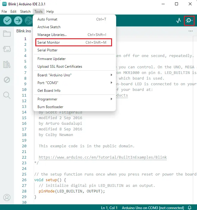
Alternatively, you can access the serial monitor by clicking on the icon located in the top-right corner of the Arduino IDE, as depicted in the image above.
Upon selecting the Serial Monitor, you will be presented with a window displaying serial data, as shown below:
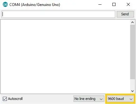
You can adjust the baud rate by selecting one of the values highlighted in the image above. If the baud rates of the two devices do not match, no data or garbage values will be received.
Arduino Serial Plotter
The Arduino IDE features a remarkable tool known as the Arduino Serial Plotter. It visualizes data received on the computer’s serial port in the form of waveforms. This functionality proves highly beneficial for data visualization, code debugging, and observing variables represented as waveforms.
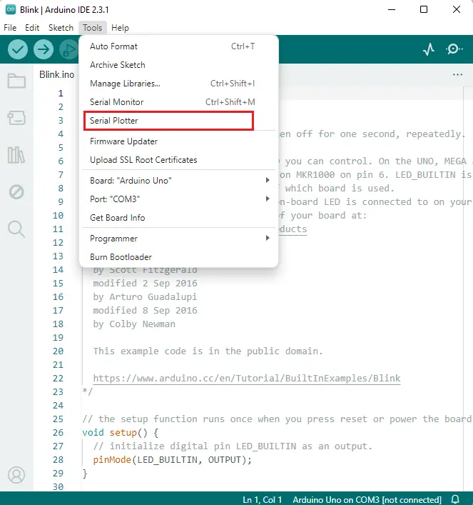
You can locate the Serial Plotter in the Arduino IDE as shown below:
Functions Used for Arduino Serial Communication
Serial.begin (baud rate)
This function initializes serial communication at a specified baud rate.
e.g. Serial.begin(9600)
Serial.print (data, format type (optional))
This function sends ASCII characters over the serial port for easy human readability. It converts the data into ASCII characters and then transmits (prints) it.
e.g. Serial.print (123);
     Serial.print (“123”);
     Serial.print (12, HEX)
Serial.println (data, format type (optional))
This function sends ASCII characters over the serial port, followed by a carriage return.
Serial.write()
This function writes binary data to the serial port and returns the number of bytes written.
e.g. Serial.write (65); // it writes actual byte to serial port
Serial.available ()
This function returns the number of bytes available to read.
Serial.read()
This function is used to read data serially.
e.g. received_data = Serial.read()
Serial.readString()
This function is used to read the received string.
e.g. String received_data = Serial.readString()
Transmitting Data to Computer Serially with Arduino
Here’s a program to transmit data serially to a computer using Arduino at a baud rate of 9600.
Sketch for Transmitting Data to the Computer:
void setup() {
    Serial.begin (9600); //initiate serial communication with 9600 baud rate
}

void loop() {
    Serial.println("hello");  //send data to computer
    delay(1000);
}
Output on Serial Monitor
Reading Data Serially from the PC and Displaying it on the Serial Monitor
In this scenario, we will transmit data serially from a PC and read it using Arduino. After reading, we will display that data on the serial monitor (PC).
Code for Reading data Serially using Arduino
char received_data;   //variable to store read data
void setup() {
  Serial.begin(9600);
}

void loop() {
  if(Serial.available()>0)  //check for any data received
  {
      received_data = Serial.read();  //read received data
      Serial.print("received data is: ");
      Serial.println(received_data);  //display received data
  }
}
Reading a Transmitted String from the PC using Arduino
Let’s create a program to read a string received from the PC and display it on the serial monitor.
Code for reading a serial string using arduino
String receive_buffer;
void setup() {
  Serial.begin(9600);
}

void loop() {
  if(Serial.available()>0)  //check for any data received
  {
      receive_buffer = Serial.readString();  //read received data
      Serial.print("received data is: ");
      Serial.println(receive_buffer);        //display received data
  }
}
Controlling an LED from the PC using Arduino
We will develop a small application where we control an LED by sending serial commands from the PC.
Code for LED Control using the PC:
char received_data;
void setup() {
  Serial.begin(9600);
  pinMode(13, OUTPUT);
}

void loop() {
  if(Serial.available()>0){
      //read serial data
      received_data = (char)Serial.read();

      Serial.print("received data is: ");

      //check for received command for action
      if(received_data=='1'){
        digitalWrite(13, HIGH);
        Serial.println(received_data);
      }
      else if(received_data=='0'){
        digitalWrite(13, LOW);
        Serial.println(received_data);
      }
      else
        Serial.println(" invalid");
    }
}
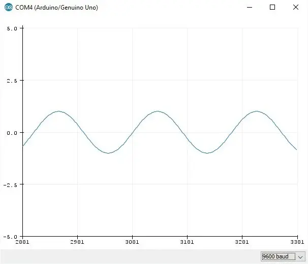
Plotting a Sinewave on the Serial Plotter
Let’s generate Sinewave and display it on serial plotter.
Code for Sinewave Generation using Arduino Uno:
void setup() {
  Serial.begin(9600);
}

void loop() {
  for (float j = 0; j < 360.00; j=j+2) {
   Serial.println(sin(j * (PI / 180.00)));    //plot sinewave
  }
}
Serial Plotter Output
Serial.print(value 1);
Serial.print(" ");
Serial.println(value 2);
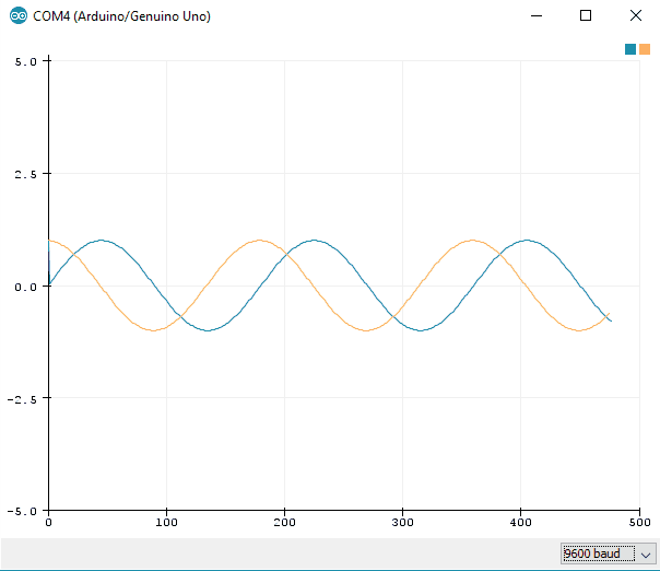
Visualizing Multiple Data on the Serial Plotter
We will generate sine and cosine signals using Arduino and transmit them to the PC at a baud rate of 9600. After transmitting data, we can visualize these signals on the Serial Plotter.
Code for Sine & Cosine Plotting using Arduino:
void setup() {
  Serial.begin(9600);
}

void loop() {
  for (float j = 0; j < 360.00; j=j+2) {
   Serial.print(sin(j * (PI / 180.00)));    //plot sinewave
   Serial.print(" ");
   Serial.println(cos(j * (PI / 180.00)));    //plot cosinewave
  }
}
Serial Plotter Output
Related article
- Mastering UART Communication Basics
- Mastering the Basics of SPI Protocol Communication
- Exploring I2C: Essential Communication Protocol Basics


