
Introduction to Analog-to-Digital Conversion (ADC)
- When connecting sensors to a microcontroller, the sensor output is often analog, whereas the microcontroller operates on digital signals.
- To bridge this gap, an ADC is employed between the sensor and microcontroller. Its function is to convert analog signals into digital ones, facilitating compatibility with the microcontroller.
- ADC finds numerous applications such as in biometric systems, environmental monitoring, and gas leakage detection.
The Arduino Uno features 6 onboard ADC channels, capable of reading analog signals within the 0-5V range. Its 10-bit ADC translates analog inputs into digital values ranging from 0 to 1023 (2^10). This range, known as resolution, signifies the number of distinct values the ADC can generate across the analog range.
Parts Required
Digital Output Value Calculation
ADC Resolution = Vref / ((2^n) – 1)
Digital Output = Vin / Resolution
Where,
Vref represents the reference voltage, indicating the maximum value the ADC can convert. For simplicity, let’s assume Vref is 5V.
For Vin = 0, the digital output value is 0. For Vin = 5, the digital output value is 1023 (10-bit). For Vin = 2.5, the digital output value is 512 (10-bit).
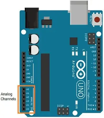
ADC Pins of Arduino Uno
Arduino ADC Analog Functions
analogRead (pin)
This function is utilized to obtain an analog value from a specified analog pin.
pin – the analog pin number from which we intend to read.
returns – a digital value ranging from 0 to 1023.
e.g. analogRead(A0) //read analog value at A0 channel
analogReference (type)
This function is employed to configure the reference voltage utilized for analog input.
let’s see How to Read Analog values using Arduino
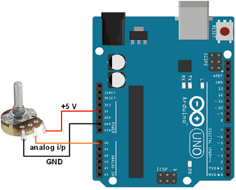
Let’s write a program to read varying analog value generated using potentiometer which is connected to A0 analog channel. Display the digital value on Serial monitor which we got from the Arduino ADC.
Potentiometer Interfacing with Arduino Uno
Arduino Code for reading analog value
int sensorPin = A0;  // input pin for the potentiometer
int digitalValue = 0;// variable to store the value coming from the sensor

void setup() {
  Serial.begin(9600);
}

void loop() {
  digitalValue = analogRead(sensorPin);// read the value from the analog channel
  Serial.print("digital value = ");
  Serial.println(digitalValue);        //print digital value on serial monitor
  delay(1000);
}
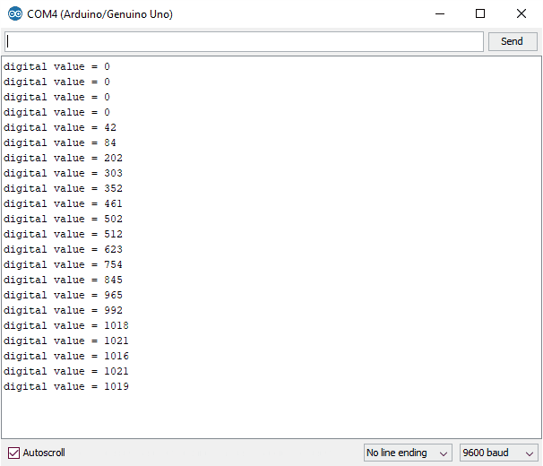
Output on Serial Monitor
Reading Analog Voltage using Arduino Uno
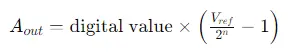
Since the Analog-to-Digital Converter (ADC) provides digital output proportional to the analog value, determining the input analog voltage requires converting this digital value back to an analog one through programming. To achieve this conversion, the formula used is:
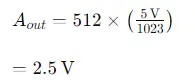
For example, if the digital value is 512 and the ADC is 10-bit with a Vref of 5V, then to find the corresponding analog voltage:
Code for Reading Analog Voltage using Arduino
int sensorPin = A0;   // select the input pin for the potentiometer
int digitalValue = 0;  // variable to store the value coming from the sensor
float analogVoltage = 0.00;

void setup() {
  Serial.begin(9600);
}

void loop() {
  digitalValue = analogRead(sensorPin);// read the value from the analog channel
  Serial.print("digital value = ");
  Serial.print(digitalValue);        //print digital value on serial monitor
  //convert digital value to analog voltage
  analogVoltage = (digitalValue * 5.00)/1023.00;
  Serial.print("  analog voltage = ");
  Serial.println(analogVoltage);
  delay(1000);
}
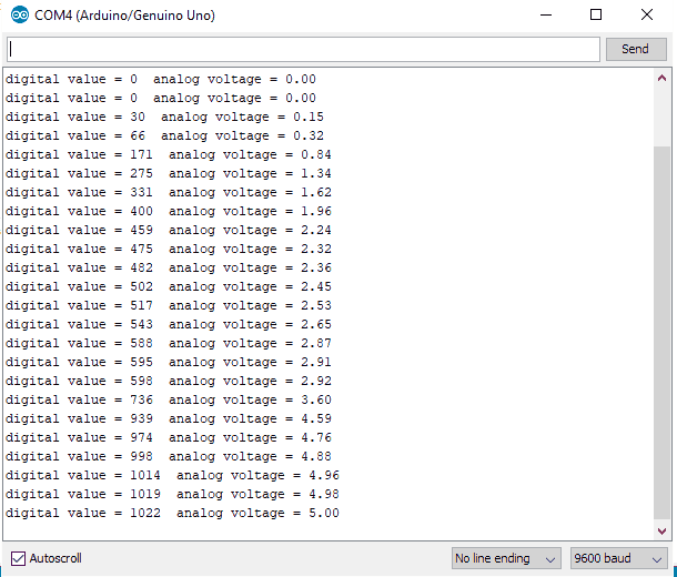
Output on Serial Window
Related article
- Mastering UART Communication Basics
- Mastering the Basics of SPI Protocol Communication
- Exploring I2C: Essential Communication Protocol Basics
- Serial Communication Essentials: Delving into Arduino USART


