
Introduction to PWM
Pulse Width Modulation (PWM) is a method that alters the width of a pulse while maintaining a constant frequency. It serves as a means to create an analog signal utilizing digital origins.

In PWM, a signal is characterized by two primary elements: the duty cycle and the frequency.
Understanding Signal Duty Cycle
The duty cycle of a signal refers to the proportion of time during a pulse period that the signal remains in an ON state (at 5V) compared to the total period, which includes both ON and OFF states.
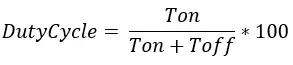
For example, if a pulse has a period of 10ms and remains ON for 2ms, the duty cycle is calculated as follows:
D = (2ms / 10ms) * 100% = 20%
By employing PWM technique, we can regulate the power supplied to a load using an ON-OFF signal. PWM signals find application in controlling the speed of DC motors and adjusting the brightness of LEDs.
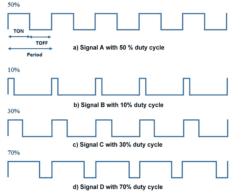
Different pulse width modulated signals with varying duty cycles are depicted below.
Signal Frequency
The frequency of a signal determines the rate at which PWM completes a cycle, for instance, 1000 Hz denotes 1000 cycles per second. This rate signifies how swiftly the signal toggles between ON (high) and OFF (low) states. By repeatedly executing this ON-OFF sequence at a rapid pace, coupled with a specific duty cycle, the output mimics the behavior of a steady voltage analog signal when supplying power to devices.
For instance, to generate a 2V analog signal from a digital source that can either be high (at 5V) or low (at 0V), PWM with a duty cycle of 40% can be employed. This means the output will be at 5V for 40% of the time. When the digital signal cycles rapidly enough, the voltage observed at the output appears to be the average voltage. Typically, if the digital low is 0V, the average voltage can be computed by multiplying the digital high voltage by the duty cycle, i.e., 5V × 0.4 = 2V.
Now, let’s delve into PWM in Arduino.
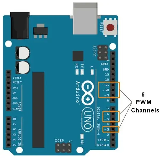
PWM Pins on Arduino Uno
The Arduino Uno is equipped with 6 channels capable of 8-bit PWM. Pins marked with the symbol ‘~’ indicate their PWM support. These PWM-enabled pins are illustrated in the image below.
Parts Required
Arduino PWM Functions
analogWrite (pin, duty cycle)
This function is utilized to produce PWM signals or output analog values to a specified PWM channel.
pin – denotes the pin where PWM or analog signal generation is desired.
duty cycle – ranges from 0 (0%, always off) to 255 (100%, always on).
e.g. analogWrite (3, 127) //generates pwm of 50% duty cycle
LED Fading with Arduino PWM
Let’s develop a simple application where an LED fades continuously. This LED fading feature is commonly used for decorative purposes during events and festivals.
Connecting LED to Arduino Uno
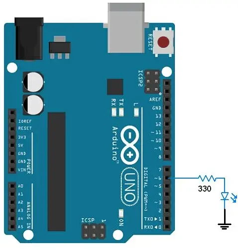
Code for LED fading utilizing Arduino PWM
int led = 6;           // the PWM pin the LED is attached to
int brightness = 0;    // how bright the LED is
int fadeAmount = 5;    // how many points to fade the LED by

void setup() {
  pinMode(led, OUTPUT); // declare pwm pin to be an output:
}

void loop() {
  analogWrite(led, brightness); // set the brightness of led

  // change the brightness for next time through the loop:
  brightness = brightness + fadeAmount;

  // reverse the direction of the fading at the ends of the fade:
  if (brightness <= 0 || brightness >= 255) {
    fadeAmount = -fadeAmount;
  }
  delay(30);  // wait for 30 milliseconds to see the dimming effect
}
Controlling LED Brightness with a Potentiometer
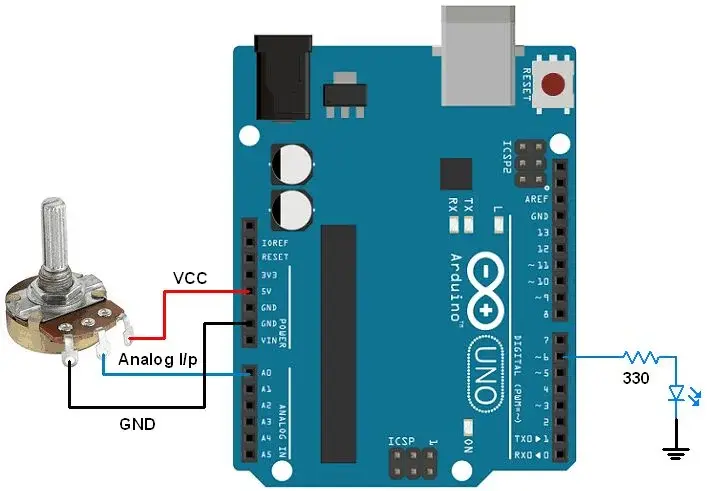
Let’s develop an application where we adjust the brightness of an LED using Arduino by manipulating a potentiometer knob. As we rotate the potentiometer knob, the Arduino’s Analog-to-Digital Converter (ADC) will interpret this analog signal. Subsequently, we’ll generate a PWM signal proportional to this analog input.
Connection Diagram
Code for LED Brightness Control using Arduino
int ledPin = 6;      // LED connected to digital pin 9
int analogPin = A0;  // potentiometer connected to analog pin 3
int val = 0;         // variable to store the read value

void setup()
{
  pinMode(ledPin, OUTPUT);   // sets the pin as output
}

void loop()
{
  val = analogRead(analogPin); // read the input pin
  analogWrite(ledPin, val / 4);// analogRead values go from 0 to 1023, analogWrite values from 0 to 255
}
Related article
- Mastering Analog-to-Digital Conversion (ADC) in Arduino
- Mastering UART Communication Basics
- Mastering the Basics of SPI Protocol Communication
- Exploring I2C: Essential Communication Protocol Basics
- Serial Communication Essentials: Delving into Arduino USART


