
Introduction to GPIO
General-Purpose Input Output (GPIO) refers to a digital pin found on an integrated circuit (IC). It serves the purpose of either accepting input from external devices or producing output for interfacing with other components.
When utilized for reading data from switches, sensors, etc., GPIO pins are configured as input. Conversely, when employed to regulate LED brightness, motor rotation, displaying text on a screen, etc., they are configured as output.
Parts Required
Arduino Uno GPIO Pin Diagram
The Arduino Uno board encompasses several digital input/output (IO) pins, facilitating the connection of various devices for input or output functions. The image below illustrates the digital IO pins of the Arduino Uno.
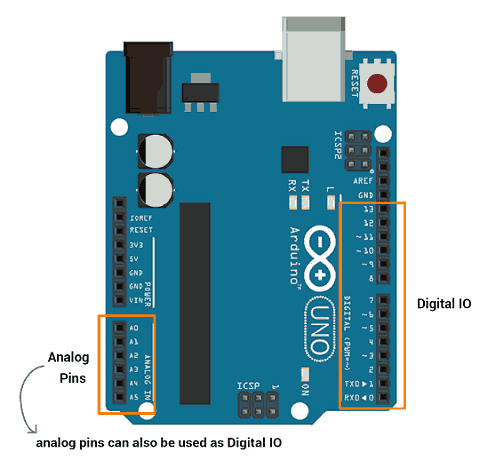
Additionally, Arduino’s analog pins can also function as digital input/output pins. Let’s delve into the digital input and output capabilities of the Arduino (ATmega).
Digital Output
Arduino (ATmega) digital pins can be configured as outputs to drive external output devices. These pins must be specifically set up for output functionality.
To configure these pins, the pinMode() function is utilized, which defines whether the pin will act as an input or an output.
pinMode(pin no, Mode)
This function is employed to establish the mode of a GPIO pin as either input or output.
pin no: The numerical designation of the pin whose mode is to be configured.
Mode: Specifies whether the pin will be set as INPUT, OUTPUT, or INPUT_PULLUP.
pinMode (3, OUTPUT) //set pin 3 as output
Arduino (ATmega) pins designated as outputs can supply or sink current up to 40 mA, which is adequate for driving LEDs and LCD displays but insufficient for powering motors, relays, etc.
These pins produce output signals categorized as either HIGH (5 V or 3.3 V) or LOW (0 V). The digitalWrite() function is employed to set the output level of these pins.
digitalWrite(pin no, Output value)
This function is utilized to set the output of a pin to either HIGH (5 V) or LOW (0 V).
pin no: The numerical designation of the pin whose output is to be set.
Output value: Specifies whether the output should be set as HIGH or LOW.
For instance, digitalWrite(3, HIGH) sets pin 3’s output to HIGH.
Digital Input
To retrieve data from sensors or any other device/circuit, it’s necessary to configure the digital pin as an input. Arduino pins are set as digital inputs by default, eliminating the need for explicit configuration.
The pinMode() function is utilized to configure a pin as a digital input. Data from a GPIO pin can be obtained using the digitalRead() function.
- digitalRead(pin)
This function reads data from the specified GPIO pin.
Digital Input with Pull-up Resistor
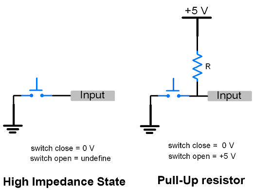
- Occasionally, when transitioning between states or when pins configured as inputs have no external connections, a high-impedance state, also known as a floating state, may occur. This state can result in erratic changes in pin state.
- To prevent this situation, pull-up resistors (connected to +5V) or pull-down resistors (connected to ground) can be added to establish the input at a defined state. The image below illustrates the high-impedance state and the application of a pull-up resistor.
- Arduino (ATmega) incorporates built-in configurable pull-up resistors. These resistors can be activated by using pinMode() with the mode set to INPUT_PULLUP. When connecting a device or sensor to a pin configured as an input with a pull-up resistor, the other end should be connected to ground.
pinMode(3, INPUT_PULLUP)
- Input pull-up can also be configured differently. Setting the pin direction as input and subsequently writing a HIGH value to the pin activates the pull-up resistor. Similarly, writing HIGH to a pin configured as OUTPUT and then configuring it as an input also activates the pull-up resistor.
pinMode (3, INPUT)        //set pin as input

digitalWrite (3, HIGH)            //setting high on input pin enables pullup
Blinking an LED Using Arduino
Let’s create a program to blink the onboard LED of the Arduino Uno. The onboard LED is connected to digital pin 13.
Arduino Code for LED Blinking
void setup()
{
  pinMode(13, OUTPUT);          // sets the digital pin 13 as output
}

void loop()
{
  digitalWrite(13, HIGH);       // sets the digital pin 13 on
  delay(1000);                  // waits for a second
  digitalWrite(13, LOW);        // sets the digital pin 13 off
  delay(1000);                  // waits for a second
}
LED Blinking Output using Arduino Uno
Sequential LED On-Off Control using Arduino
Let’s control the LEDs sequentially, turning them on and off one after the other. Initially, we will turn on four LEDs one by one. This means LED1 will be turned on first, followed by LED1 and LED2, and so forth. When all four LEDs are turned on, we will then turn them off in reverse sequence, one by one. This entails turning off LED4 first, then LED3, and so on.
Four LEDs are connected to pins 0 to 3 of the Arduino Uno.
Sequential LED ON-OFF code using Arduino uno
void setup() {

//set gpio pin {0,1,2,3} as output
pinMode(0, OUTPUT);
pinMode(1, OUTPUT);
pinMode(2, OUTPUT);
pinMode(3, OUTPUT);
}

void loop() {
  //turn LED ON one by one
  for(int i=0;i<4;i++){
    digitalWrite(i, HIGH);
    delay(1000);
  }

  //turn LED OFF one by one
  for(int i=3;i>=0;i--){
    digitalWrite(i, LOW);
    delay(1000);
  }
}
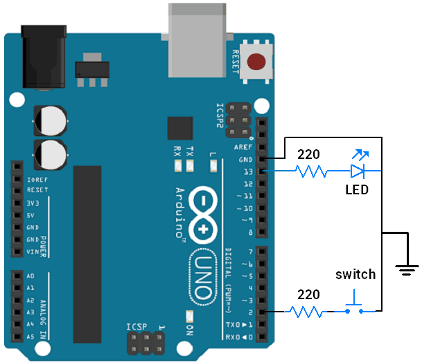
Control LED with Switch using Arduino
Let’s control the LED on-off functionality using a switch interfaced with the Arduino Uno.
LED and Switch connection diagram with Arduino Uno
Control LED with a Switch using Arduino Code
int pushButton = 2;
int LED = 13;

void setup() {
  // make the pushbutton's pin an input:
  pinMode(pushButton, INPUT_PULLUP);  //configure pin as input with pullup enabled
  pinMode(LED, OUTPUT);               //configure pin as output
}

void loop() {
  // read the input pin:
  int buttonState = digitalRead(pushButton);

  digitalWrite(LED, (!(buttonState))); //turn len on when switch pressed

  delay(1);        // delay in between reads for stability
}
Related article
- Beginner’s Guide to PWM Control with Arduino
- Mastering Analog-to-Digital Conversion (ADC) in Arduino
- Mastering UART Communication Basics
- Mastering the Basics of SPI Protocol Communication
- Exploring I2C: Essential Communication Protocol Basics
- Serial Communication Essentials: Delving into Arduino USART


