

For basic single-stepper-motor applications, a driver such as the L298N is sufficient. However, if you intend to create more complex projects like a CNC machine or 3D printer, you’ll need a specialized stepper motor driver like the DRV8825.
The DRV8825 driver offers straightforward control over stepper motors and provides a wide range of stepping modes, making it an excellent choice for applications that demand precise and reliable stepper motor controller. It proves especially beneficial for tasks involving the movement control of beds, heads, and assemblies in various CNC plotting, milling, and 3D printer designs.
One of the significant advantages of the DRV8825 is its ability to control a bipolar stepper motor arduino, like the NEMA 17, using just two pins for speed and direction adjustments. This streamlined setup simplifies the control process and enhances overall efficiency.
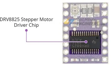
DRV8825 Stepper Motor Driver Chip
The DRV8825 is a stepper motor driver chip manufactured by Texas Instruments. Despite its small size, measuring 0.8″ x 0.6″, it offers impressive performance for driving bipolar stepper motors.
One of the key features of the DRV8825 is its high output drive capacity, capable of handling voltages up to 45V. This allows for precise control of bipolar stepper motors, such as the popular NEMA 17, with a maximum output current of up to 2.5A per coil.
The driver’s regulated output current ensures smooth and noiseless operation of the stepper motor, reducing resonance and ringing commonly experienced in drivers without such regulation.
Controlling the stepper motor with the DRV8825 is straightforward, as it comes with a built-in translator, reducing the number of control pins required to just two—one for step control and the other for direction control.
Another advantage of the DRV8825 arduino is its flexibility in step resolution, offering six different options ranging from full-step to thirty-second-step, allowing for fine-tuned control of motor movements.
To ensure safe and reliable operation, the DRV8825 incorporates various protective features, including under-voltage, shoot-through, short circuit, overcurrent, and thermal protection. These features contribute to the chip’s reliability and prevent damage to the stepper motor arduino and driver under various operating conditions.
Technical Specifications
Here are the specifications:
| Motor output voltage | 8.2V – 45V |
| Logic voltage | Built-In 3.3V output |
| Continuous current per phase | 1A |
| Maximum current per phase | 2.5A |
| Microstep resolution | full, 1/2, 1/4, 1/8, 1/16, and 1/32 |
For more information, please refer to the datasheet below.
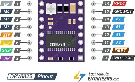
DRV8825 Motor Driver Pinout
The DRV8825 stepper motor driver features a pinout with 16 pins connecting it to the external components. Let’s explore each pin:
Power Pins
The DRV8825 stepper motor driver has two power-related pins:
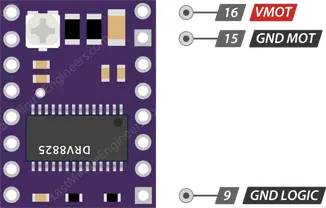
VMOT: This pin is used to supply power to the stepper motor. It accepts a voltage range between 8.2V and 45V. It is important to provide an appropriate voltage within this range to ensure proper motor operation.
GND MOT: This pin is the ground connection for the motor power supply. It completes the circuit for the motor and should be connected to the ground of the power supply.
Unlike some other stepper motor drivers, the DRV8825 only requires these two power supply connections for the motor. The logic circuitry of the DRV8825 draws power from the motor power supply using an internal 3.3V voltage regulator. Therefore, the DRV8825 does not have a separate logic supply pin, and you should connect your microcontroller’s or logic system’s ground to the GND LOGIC pin for proper communication between the driver and the controlling device.
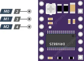
Microstep Selection Pins
The DRV8825 stepper motor driver supports microstepping, which allows a single step to be divided into smaller steps, providing smoother and more precise motion for the stepper motor. The microstep selection is controlled using three pins: M0, M1, and M2.
These three microstep selection pins allow you to choose from six different step resolutions, ranging from full-step to 1/32-step. The microstep resolutions and their corresponding logic level configurations for M0, M1, and M2 are as follows:
| M0 | M1 | M2 | Microstep Resolution |
| Low | Low | Low | Full step |
| High | Low | Low | Half step |
| Low | High | Low | 1/4 step |
| High | High | Low | 1/8 step |
| Low | Low | High | 1/16 step |
| High | Low | High | 1/32 step |
| Low | High | High | 1/32 step |
| High | High | High | 1/32 step |
If you leave the microstep selection pins unconnected, they will be pulled LOW by internal pull-down resistors, and the driver will operate in full-step mode.
By selecting a specific microstep resolution, you can control the smoothness and precision of the stepper motor’s movements. Higher microstep resolutions generally result in smoother motion but require more processing power and may reduce the maximum achievable motor speed. On the other hand, lower microstep resolutions provide less smoothness but allow for higher speeds. The appropriate microstep resolution depends on the specific application’s requirements for precision and speed.
Control Input Pins
The DRV8825 stepper motor driver has two control input pins: STEP and DIR.
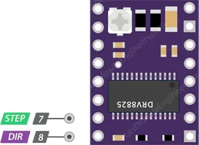
STEP Pin: The STEP pin controls the microsteps of the motor. Each rising edge (HIGH pulse) sent to this pin causes the driver to take one step, as determined by the microstep selection pins (M0, M1, and M2). The more pulses applied per unit time, the faster the motor will rotate. Controlling the STEP pin allows precise control over the stepper motor’s movement, enabling smooth and accurate motion.
DIR Pin: The DIR pin controls the spinning direction of the motor. When the DIR pin is set HIGH, the motor rotates in one direction (usually clockwise), and when set LOW, it rotates in the opposite direction (usually counterclockwise). By changing the logic level on the DIR pin, you can easily reverse the direction of rotation, allowing the motor to move forward and backward as required for the application.
Together, the STEP and DIR pins enable precise control over the stepper motor’s speed and direction. By pulsing the STEP pin at different frequencies and changing the state of the DIR pin, you can achieve complex and controlled movements for various applications such as robotics, CNC machines, 3D printers, and more. The simplicity of this control method, with only two input pins, makes the DRV8825 driver an ideal solution for applications that require reliable and accurate arduino stepper motor control.
Pins For Controlling Power States
The DRV8825 stepper motor driver has three separate input pins for controlling its power states: EN, RST, and SLP.
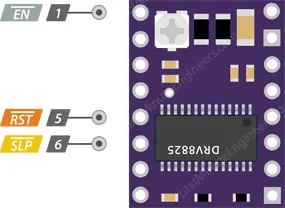
EN (Enable) Pin: The EN pin is an active-low input pin. When this pin is pulled LOW (connected to GND), the DRV8825 driver is enabled, allowing it to operate and control the connected stepper motor arduino. By default, the EN pin is internally pulled low, meaning that the driver is enabled without any external connection. If you want to disable the driver temporarily or implement an emergency stop/shutdown system, you can pull the EN pin HIGH (connect to VCC).
RST (Reset) Pin: The RST pin is also an active-low input. When this pin is pulled LOW (connected to GND), it performs a reset function on the DRV8825 driver. This action sets the internal translator to a predefined “home” state, which is the initial position for the motor, and it varies based on the microstep resolution selected using the M0, M1, and M2 pins. Connecting RST to GND will reset the driver, and it can be particularly useful for specific applications where a reset is needed.
SLP (Sleep) Pin: The SLP pin is an active-low input that puts the DRV8825 driver into sleep mode when pulled LOW (connected to GND). In sleep mode, the driver reduces power consumption to a minimum, making it useful for saving power when the motor is not actively in use or when the system is idle. To wake up the driver from sleep mode and resume normal operation, you need to pull the SLP pin HIGH (connect to VCC). After waking up the driver, it’s important to provide a 1 ms delay before issuing a Step command to allow the charge pump to stabilize.
Managing the EN, RST, and SLP pins allows you to control the power state of the DRV8825 driver effectively, enabling you to enable, disable, reset, or put the driver to sleep based on the requirements of your application. These pins offer additional flexibility and control, making the DRV8825 driver suitable for a wide range of stepper motor controller applications.
Fault Detection Pin
The DRV8825 stepper motor driver has a Fault Detection Pin, labeled as FAULT. This pin serves as an output and provides information about the driver’s status, specifically indicating if certain fault conditions have occurred.
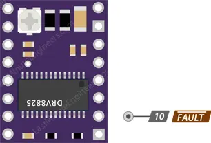
When the H-bridge FETs (Field-Effect Transistors) in the DRV8825 driver are disabled due to over-current protection or thermal shutdown, the FAULT pin is driven LOW. This indicates that a fault event has been triggered, and the driver is temporarily disabled to protect it from potential damage.
Typically, the FAULT pin is connected or shorted to the SLP (Sleep) pin on the driver board. When the FAULT pin is driven LOW, it disables the entire chip, and the driver remains inactive until the condition causing the fault is resolved.
To restore the operation of the driver after a fault event, you can either perform a RESET or remove and reapply the motor voltage (VMOT). This will clear the fault condition, and the driver will be ready to operate normally again.
The FAULT Detection Pin is a useful feature that enhances the safety and protection of the stepper motor driver and the connected motor, helping prevent potential damage caused by over-current or thermal issues. By monitoring the FAULT pin, you can implement appropriate error-handling procedures and ensure the reliable and safe operation of your stepper motor system.
Output Pins
The DRV8825 stepper motor driver has four output pins, labeled as B2, B1, A1, and A2. These output pins are used to connect the driver to a bipolar stepper motor arduino.
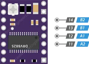
You can connect any small to medium-sized bipolar stepper motor, such as NEMA 17, to these output pins. The motor coils are typically connected to these pins in a specific pattern to control the motor’s movement.
By pulsing these output pins in a specific sequence, the DRV8825 driver can energize the motor coils in a controlled manner, causing the stepper motor to step and rotate in a precise manner.
Each output pin can supply up to 2.5A of current to the motor. However, the amount of current supplied to the motor depends on the power supply, cooling system, and current limiting setting of the system. Properly setting the current limit ensures the motor receives the appropriate amount of current for its safe and efficient operation.
The output pins are a crucial part of the DRV8825 driver as they enable precise control over the stepper motor’s movement, making it suitable for various applications, including CNC machines, 3D printers, robotics, and automation systems. By connecting the stepper motor to these output pins, you can utilize the full capabilities of the DRV8825 stepper motor driver to achieve accurate and reliable motor control.
Cooling System – Heatsink
The DRV8825 driver IC generates heat during operation, which can potentially cause damage if not properly managed. Despite having a maximum current rating of 2.5A per coil, the DRV8825 driver IC can only supply about 1.5A per coil without overheating. To achieve higher currents up to the maximum rating, it is essential to use a heat sink or other effective cooling methods.
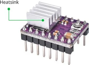
Fortunately, the DRV8825 driver module often comes with a heatsink included. Installing the heatsink before using the driver is highly recommended as it helps dissipate heat efficiently, ensuring the driver operates within safe temperature limits and maintaining reliable performance.
Current limiting
Before running the motor, you must limit the maximum current flowing through the stepper coils so that it does not exceed the motor’s rated current.
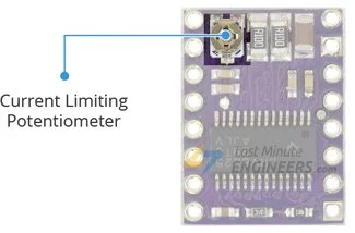
The DRV8825 driver includes a small trimmer potentiometer for setting the current limit.
There are two methods for making this adjustment:
Method 1:
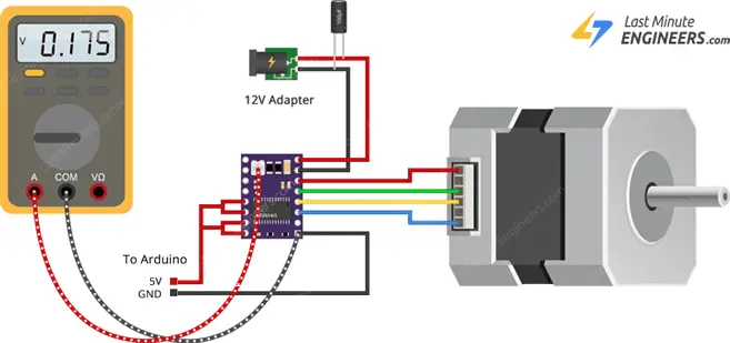
In Method 1, the current limit for the stepper motor is set by measuring the voltage (Vref) at the “ref” pin of the DRV8825 arduino driver.
- Refer to the datasheet of your stepper motor and note its rated current. For example, let’s assume we have a NEMA 17 stepper motor with a rated current of 350mA at 200 steps/revolution and 12V.
- To ensure the driver is in full-step mode, disconnect the three microstep selection pins.
- With the motor held stationary and the STEP input not activated, measure the voltage (Vref) on the metal trimmer potentiometer.
- To calculate the appropriate Vref voltage, use the formula Vref = Current Limit / 2. For a motor rated at 350mA, the reference voltage would be set to 0.175V.
- A convenient way to make this adjustment is by connecting one end of an alligator clip test lead to the shank of a metal screwdriver and the other end to your multimeter. This allows you to measure the voltage while making adjustments.
- By adjusting the metal trimmer potentiometer, set the Vref voltage to match the desired current limit for your stepper motor (0.175V for 350mA in our example). This ensures that the motor operates within its safe current limits and prevents overheating or damage to the motor and driver.
Method 2:
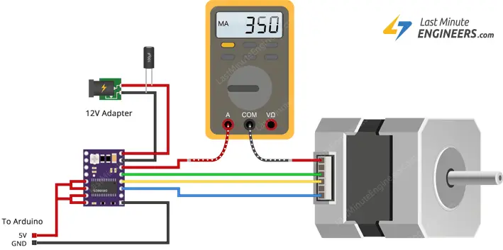
In Method 2, the current limit for the stepper motor is determined by directly measuring the current flowing through one of the coils.
- Refer to the datasheet of your stepper motor and note its rated current. For instance, let’s consider a NEMA 17 stepper motor with a rated current of 350mA at 200 steps/revolution and 12V.
- To ensure the driver is in full-step mode, disconnect the three microstep selection pins.
- With the motor held stationary and the STEP input not activated, put an ammeter in series with one of the coils on your stepper motor to measure the actual current flowing.
- Take a small screwdriver and locate the current limit potentiometer on the DRV8825 driver.
- Gradually adjust the current limit potentiometer while monitoring the ammeter reading until it reaches the desired rated current for your stepper motor (350mA in our example).
- Once the current limit is set correctly, the driver will ensure that the motor operates within its safe current range, preventing excessive current flow that could lead to overheating or damage to the motor and driver.
By using this method, you can accurately adjust the current limit to match the requirements of your stepper motor, ensuring smooth and reliable operation for your specific application.
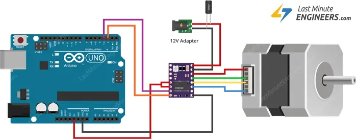
Wiring a DRV8825 Stepper Motor Driver to an Arduino
To connect a DRV8825 Stepper Motor Driver to an Arduino, follow these steps:
- Connect RST and SLP/SLEEP: Join the RST pin of the DRV8825 to the adjacent SLP/SLEEP pin and connect both of them to the 5V pin on the Arduino. This setup keeps the driver enabled.
- Connect GND LOGIC: Attach the GND LOGIC pin of the DRV8825 to the GND (ground) pin on the Arduino.
- Connect DIR and STEP: Connect the DIR (direction) and STEP (stepping) pins of the DRV8825 to two digital output pins on the Arduino. You can use pins #2 and #3, for example.
- Connect the Stepper Motor: The DRV8825 module is designed to match the standard 4-pin connector found on bipolar stepper motor arduino. Connect the motor’s wires to the B2, B1, A1, and A2 pins on the DRV8825 arduino.
Warning:
- Avoid connecting or disconnecting the stepper motor while the driver is powered on, as this could damage the driver.
- If you want to run the motor in full-step mode, leave the microstep selection pins (M0, M1, M2) disconnected.
Power Supply: Connect the motor power supply to the VMOT and GND MOT pins on the DRV8825 module. Ensure that the power supply voltage falls within the specified range (8.2V to 45V). To prevent voltage spikes, add a large 100μF decoupling electrolytic capacitor across the motor power supply pins.
Once everything is properly connected, you can control the stepper motor using the Arduino by sending appropriate signals to the DIR and STEP pins. Remember to set the current limit of the driver according to the rated current of your stepper motor using one of the two methods mentioned earlier (measuring Vref or measuring the current flowing through the coil).
Parts Required
| Component Name | Buy Now |
| Arduino Uno REV3 | Amazon |
| DRV8825 Stepper Motor Driver Module | Amazon |
| Nema 17 Stepper Motor Bipolar 2A 59Ncm(84oz.in) | Amazon |
| Breadboard | Amazon |
| BOJACK 1000 Pcs 25 Values Resistor Kit 1 Ohm-1M Ohm with 5% 1/4W | Amazon |
Arduino Code – Without a Library
The following sketch demonstrates how to control the speed and spinning direction of a bipolar stepper motor using the DRV8825 stepper motor driver. It can serve as a foundation for practical experiments and projects.
// Define pin connections & motor's steps per revolution
const int dirPin = 2;
const int stepPin = 3;
const int stepsPerRevolution = 200;

void setup()
{
	// Declare pins as Outputs
	pinMode(stepPin, OUTPUT);
	pinMode(dirPin, OUTPUT);
}
void loop()
{
	// Set motor direction clockwise
	digitalWrite(dirPin, HIGH);

	// Spin motor slowly
	for(int x = 0; x < stepsPerRevolution; x++)
	{
		digitalWrite(stepPin, HIGH);
		delayMicroseconds(2000);
		digitalWrite(stepPin, LOW);
		delayMicroseconds(2000);
	}
	delay(1000); // Wait a second

	// Set motor direction counterclockwise
	digitalWrite(dirPin, LOW);

	// Spin motor quickly
	for(int x = 0; x < stepsPerRevolution; x++)
	{
		digitalWrite(stepPin, HIGH);
		delayMicroseconds(1000);
		digitalWrite(stepPin, LOW);
		delayMicroseconds(1000);
	}
	delay(1000); // Wait a second
}
This code snippet controls the DRV8825 driver to rotate the stepper motor first in a clockwise direction at a slower speed, and then counterclockwise at a faster speed. The dirPin sets the spinning direction (HIGH for clockwise, LOW for counterclockwise), and the stepPin generates pulses to move the motor one step at a time. The delayMicroseconds function is used to control the timing between steps, allowing you to adjust the motor’s speed. The loop then waits for a second before reversing the motor’s direction and repeating the process.
Code Explanation:
In this section, we declare three constants: dirPin, stepPin, and stepsPerRevolution. dirPin and stepPin represent the Arduino’s digital output pins connected to the DRV8825 driver’s DIR and STEP inputs, respectively. stepsPerRevolution specifies the number of steps required for one complete revolution of the stepper motor arduino.
const int dirPin = 2;
const int stepPin = 3;
const int stepsPerRevolution = 200;
In the setup function, we configure the dirPin and stepPin as outputs using the pinMode function. This setup is necessary to control the direction and stepping of the stepper motor.
pinMode(stepPin, OUTPUT);
pinMode(dirPin, OUTPUT);
We set the dirPin to HIGH, which means the motor will rotate in a clockwise direction.
digitalWrite(dirPin, HIGH);
This loop will execute stepsPerRevolution times, causing the stepper motor to complete one full revolution. Inside the loop:
for(int x = 0; x < stepsPerRevolution; x++) {
	digitalWrite(stepPin, HIGH);
	delayMicroseconds(1000);
	digitalWrite(stepPin, LOW);
	delayMicroseconds(1000);
}
Arduino Code – Using AccelStepper library
Using the AccelStepper library in Arduino allows for more sophisticated control of stepper motors, especially when dealing with multiple motors simultaneously. While simple applications with a single motor can be managed without a library, more complex projects will benefit from the features offered by this advanced library.
For our upcoming experiment, we will integrate the AccelStepper library into our project. This library offers the following capabilities:
- Acceleration and deceleration of stepper motors, enabling smoother and more precise movements.
- Support for controlling multiple steppers at the same time, each independently stepping with its specific pattern.
Library Installation
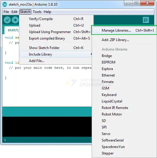
Before using the AccelStepper library, you need to ensure it is installed in your Arduino IDE:
Navigate to “Sketch” and select “Include Libraries” and then “Manage Libraries…”
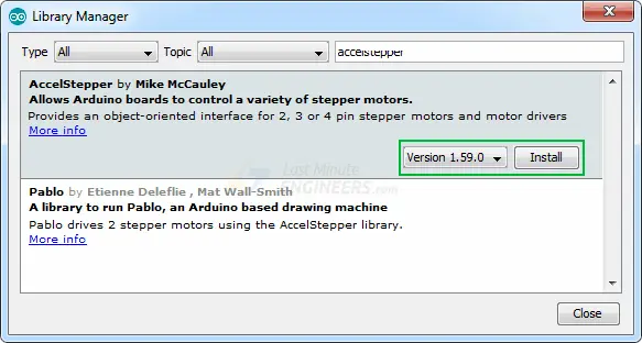
Wait for the Library Manager to download the library index and update the list of available libraries.
Filter your search by typing “accelstepper”.
Click on the first entry and select “Install” to add the AccelStepper library to your Arduino environment.
Arduino Code
Below is the Arduino code for a simple sketch that accelerates a stepper motor in one direction, then decelerates to come to a stop. After completing one revolution, the motor changes its spinning direction and repeats the process.
// Include the AccelStepper Library
#include <AccelStepper.h>

// Define pin connections
const int dirPin = 2;
const int stepPin = 3;

// Define motor interface type
#define motorInterfaceType 1

// Creates an instance
AccelStepper myStepper(motorInterfaceType, stepPin, dirPin);

void setup() {
	// set the maximum speed, acceleration factor,
	// initial speed and the target position
	myStepper.setMaxSpeed(1000);
	myStepper.setAcceleration(50);
	myStepper.setSpeed(200);
	myStepper.moveTo(200);
}

void loop() {
	// Change direction once the motor reaches target position
	if (myStepper.distanceToGo() == 0)
		myStepper.moveTo(-myStepper.currentPosition());

	// Move the motor one step
	myStepper.run();
}
Code Explanation:
This line includes the AccelStepper library, which provides functions to control stepper motors with acceleration and deceleration capabilities.
#include <AccelStepper.h>
These lines define the digital pin numbers for the DIR (direction) and STEP signals of the stepper motor, respectively.
// Define pin connections
const int dirPin = 2;
const int stepPin = 3;
This line defines a constant called motorInterfaceType with a value of 1, which indicates the type of stepper motor driver interface being used. In this case, it represents a driver with a simple digital step and direction control interface.
#define motorInterfaceType 1
This line creates an instance of the AccelStepper class named myStepper. It specifies the motor interface type (1), the step pin, and the direction pin as constructor arguments.
AccelStepper myStepper(motorInterfaceType, stepPin, dirPin);
This is the setup function, which runs once when the Arduino starts up. It is used to initialize variables and configure settings.
myStepper.setMaxSpeed(1000);: Sets the maximum speed of the stepper motor to 1000 steps per second. This controls how fast the motor can move.myStepper.setAcceleration(50);: Sets the acceleration of the stepper motor to 50 steps per second per second. This determines how quickly the motor can change its speed.myStepper.setSpeed(200);: Sets the initial speed of the stepper motor to 200 steps per second. This is the speed at which the motor starts moving.myStepper.moveTo(200);: Tells the stepper motor to move to the position of 200 steps. This is the target position the motor will try to reach.
void setup() {
	myStepper.setMaxSpeed(1000);
	myStepper.setAcceleration(50);
	myStepper.setSpeed(200);
	myStepper.moveTo(200);
}
- This is the loop function, which runs repeatedly after the setup function. It contains the main control logic for the stepper motor.
if (myStepper.distanceToGo() == 0) myStepper.moveTo(-myStepper.currentPosition());: This line checks if the motor has reached its target position (distanceToGo()returns 0). If it has, it reverses the direction of the motor by setting the target position to the negative value of the current position.myStepper.run();: This line moves the stepper motor one step based on its current speed and direction. It should be called repeatedly in the loop to keep the motor moving.
In summary, this code sets up a stepper motor with acceleration and deceleration using the AccelStepper library. The motor accelerates, moves to a target position of 200 steps, decelerates to a stop, then reverses direction and repeats the process in a loop.
void loop() {
	if (myStepper.distanceToGo() == 0)
		myStepper.moveTo(-myStepper.currentPosition());

	myStepper.run();
}
Related article
- Servo Motor Basics: How It Works and Arduino Interface Guide
- Interfacing DC Motors with Arduino using L298N Motor Driver Module
- Interfacing 28BYJ-48 Stepper Motor Arduino using ULN2003 Driver
- Arduino Motor Control: DRV8833 Motor Driver for DC Motors
- Arduino Motor Control: L293D Motor Driver for DC Motors
- Step-by-Step Guide: L293D Stepper Motor Driver with Arduino


This is a great detailed operation of the DRV8825 Stepper chip.
I used your sketch without a Library and got my stepper to run. Very satisfying to see.
Especially since my parts were hobbled together from various sources. I’m using a NEMA17 with a planetary gear box. This was better explained than other arduino websites for this same chip. Thank you.