

This guide demonstrates the process of managing both the direction and velocity of a DC motor utilizing an ESP32 alongside the L298N Motor Driver. Initially, we’ll provide an overview of the functionality of the L298N motor driver. Subsequently, an illustration will be presented on regulating the speed and direction of a DC motor utilizing the L298N motor driver with the ESP32 motor control programmed via the Arduino IDE.
Introducing the L298N Motor Driver
There are various methods to control a DC motor, and the one we’ll explore here is suitable for most hobbyist motors requiring 6V or 12V power.
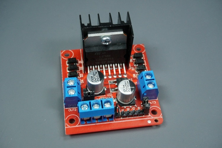
We’ll utilize the L298N motor driver capable of handling up to 3A at 35V. It enables the simultaneous control of two DC motors, making it ideal for robotics projects.
The L298N motor driver, depicted in the figure below, features a pinout configuration:
L298N Motor Driver pinout
Let’s delve into the pinout of the L298N motor driver to understand its functionality.
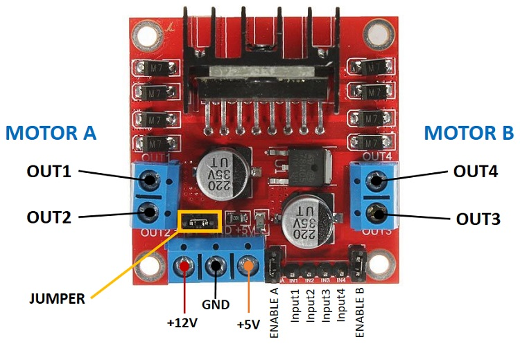
Each motor is associated with a two-terminal block on either side: OUT1 and OUT2 for motor A on the left, and OUT3 and OUT4 for motor B on the right.
- OUT1: Positive terminal of DC motor A
- OUT2: Negative terminal of DC motor A
- OUT3: Positive terminal of DC motor B
- OUT4: Negative terminal of DC motor B
At the bottom, there’s a three-terminal block with +12V, GND, and +5V. The +12V block powers the motors, while the +5V powers the L298N chip. If the jumper is connected, the chip derives power from the motor’s supply, eliminating the need for +5V input.
Important: If supplying more than 12V, remove the jumper and provide 5V to the +5V terminal.
For this tutorial, we’ll use four AA 1.5V batteries, yielding approximately 6V output. However, any suitable power source can be employed, such as a bench power supply.
In summary:
- +12V: Connect the motor’s power supply here
- GND: Ground for power supply
- +5V: Supply 5V if the jumper is removed. Acts as a 5V output if the jumper is connected.
- Jumper: With the jumper connected, the chip uses the motor’s power supply. Remove the jumper if supplying more than 12V and provide 5V to the +5V terminal.
At the bottom right are four input pins and two enable terminals. The input pins control motor direction, while the enable pins regulate motor speed.
- IN1: Input 1 for Motor A
- IN2: Input 2 for Motor A
- IN3: Input 1 for Motor B
- IN4: Input 2 for Motor B
- EN1: Enable pin for Motor A
- EN2: Enable pin for Motor B
By default, jumper caps are present on the enable pins. Remove these to control motor speed; otherwise, the motors will either remain stationary or run at maximum speed.
Control DC motors with the L298N Motor Driver
Now that you have acquainted yourself with the L298N Motor Driver, let’s explore how to utilize it for controlling your DC motors.
Enable pins
The enable pins function as ON and OFF switches for your motors. For instance:
- Sending a HIGH signal to the enable 1 pin activates motor A, operating it at maximum speed;
- Sending a LOW signal to the enable 1 pin turns off motor A;
- Applying a PWM (Pulse Width Modulation) signal allows you to regulate the motor speed. The speed is directly proportional to the duty cycle. However, it’s important to note that for low duty cycles, the motors may not spin and instead emit a continuous buzzing sound.
| SIGNAL ON THE ENABLE PIN | MOTOR STATE |
|---|---|
| HIGH | Motor enabled |
| LOW | Motor not enabled |
| PWM | Motor enabled: speed proportional to the duty cycle |
Input pins
The input pins dictate the direction of motor rotation. Input 1 and input 2 govern motor A, while input 3 and input 4 manage motor B.
When you set input1 to LOW and input 2 to HIGH, the motor will spin forward.
Conversely, if you reverse the power flow by setting input 1 to HIGH and input 2 to LOW, the motor will rotate backward. Motor B can be controlled similarly by manipulating input 3 and input 4.
For instance, for motor A, the logic follows:
| Direction | Input 1 | Input 2 | Enable 1 |
| Forward | 0 | 1 | 1 |
| Backwards | 1 | 0 | 1 |
| Stop | 0 | 0 | 0 |
Controlling 2 DC Motors – ideal to build a robot
When constructing a robot car utilizing two DC motors, it’s essential to ensure they rotate in specific directions to enable the robot to move left, right, forward, or backward.
For instance, to propel the robot forward, both motors must rotate in a forward direction. Conversely, for backward movement, both motors should rotate backward.
To execute a turn in one direction, you’ll need to increase the speed of the motor on the opposite side. For instance, to steer the robot right, activate the motor on the left while deactivating the motor on the right. The table below outlines the combinations of input pin states for various robot directions.
| DIRECTION | INPUT 1 | INPUT 2 | INPUT 3 | INPUT 4 |
|---|---|---|---|---|
| Forward | 0 | 1 | 0 | 1 |
| Backward | 1 | 0 | 1 | 0 |
| Right | 0 | 1 | 0 | 0 |
| Left | 0 | 0 | 0 | 1 |
| Stop | 0 | 0 | 0 | 0 |
Control DC Motor with ESP32 – Speed and Direction
Having learned how to manage a DC motor with the L298N motor driver, let’s proceed to construct a straightforward example for controlling both the speed and direction of a single DC motor.
Wiring a DC Motor to the ESP32 (L298N Motor Driver)
The motor we intend to control is linked to the motor A output pins. Hence, it’s imperative to connect the ENABLEA, INPUT1, and INPUT2 pins of the motor driver to the ESP32. Refer to the schematic diagram below for guidance on wiring the DC motor and the L298N motor driver to the ESP32 motor control.
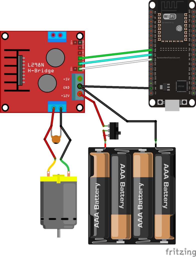
| LN298N Motor Driver | Input 1 | Input 2 | Enable | GND |
| ESP32 | GPIO 27 | GPIO 26 | GPIO 14 | GND |
We’re utilizing the GPIOs listed in the previous table to establish connections with the motor driver. However, you can employ any other suitable GPIOs, provided you modify the code accordingly. For further insights into ESP32 GPIOs, refer to the ESP32 Pinout Reference Guide.
Powering the LN298N Motor Driver
Given that the DC motor demands a substantial surge in current to initiate movement, it’s advisable to power the motors using an external power source separate from the ESP32 motor control. For instance, we’re utilizing 4 AA batteries in this demonstration, but you have the flexibility to employ any other appropriate power supply. In this setup, a power supply ranging from 6V to 12V can be utilized.
While optional, incorporating a switch between the battery holder and the motor driver proves highly advantageous. This switch facilitates convenient power cutting and application, eliminating the need for constant wire connection and disconnection to conserve power.
To mitigate voltage spikes effectively, we recommend soldering a 0.1uF ceramic capacitor to the positive and negative terminals of the DC motor, as illustrated in the diagram. Although motors function without the capacitor, its inclusion aids in smoothing out voltage fluctuations.
Code: ESP32 with DC Motor – Speed and Direction Control
The provided code enables the manipulation of both the speed and direction of the DC motor. While this code may not serve a direct practical purpose in real-world applications, it serves as an excellent illustration for comprehending the process of regulating the speed and direction of a DC motor using the ESP32 motor control.
// Motor A
int motor1Pin1 = 27;
int motor1Pin2 = 26;
int enable1Pin = 14;

// Setting PWM properties
const int freq = 30000;
const int pwmChannel = 0;
const int resolution = 8;
int dutyCycle = 200;

void setup() {
  // sets the pins as outputs:
  pinMode(motor1Pin1, OUTPUT);
  pinMode(motor1Pin2, OUTPUT);
  pinMode(enable1Pin, OUTPUT);

  // configure LED PWM functionalitites
  ledcSetup(pwmChannel, freq, resolution);

  // attach the channel to the GPIO to be controlled
  ledcAttachPin(enable1Pin, pwmChannel);

  Serial.begin(115200);

  // testing
  Serial.print("Testing DC Motor...");
}

void loop() {
  // Move the DC motor forward at maximum speed
  Serial.println("Moving Forward");
  digitalWrite(motor1Pin1, LOW);
  digitalWrite(motor1Pin2, HIGH);
  delay(2000);

  // Stop the DC motor
  Serial.println("Motor stopped");
  digitalWrite(motor1Pin1, LOW);
  digitalWrite(motor1Pin2, LOW);
  delay(1000);

  // Move DC motor backwards at maximum speed
  Serial.println("Moving Backwards");
  digitalWrite(motor1Pin1, HIGH);
  digitalWrite(motor1Pin2, LOW);
  delay(2000);

  // Stop the DC motor
  Serial.println("Motor stopped");
  digitalWrite(motor1Pin1, LOW);
  digitalWrite(motor1Pin2, LOW);
  delay(1000);

  // Move DC motor forward with increasing speed
  digitalWrite(motor1Pin1, HIGH);
  digitalWrite(motor1Pin2, LOW);
  while (dutyCycle <= 255){
    ledcWrite(pwmChannel, dutyCycle);
    Serial.print("Forward with duty cycle: ");
    Serial.println(dutyCycle);
    dutyCycle = dutyCycle + 5;
    delay(500);
  }
  dutyCycle = 200;
}
Upload the code to your ESP32, ensuring the correct board and COM port are selected. Let’s delve into the functionality of the code.
Declaring motor pins
Initially, the GPIOs to which the motor pins are linked are declared. For motor A, Input 1 is connected to GPIO 27, Input 2 to GPIO 26, and the Enable pin to GPIO 14.
int motor1Pin1 = 27;
int motor1Pin2 = 26;
int enable1Pin = 14;
Setting the PWM properties to control the speed
To regulate the speed of the DC motor using a PWM signal on the enable pin of the L298N motor driver, PWM signal properties must be configured. The speed adjustment is directly proportional to the duty cycle. To implement PWM with the ESP32, initializing PWM signal properties is necessary.
const int freq = 30000;
const int pwmChannel = 0;
const int resolution = 8;
int dutyCycle = 200;
In this instance, a signal of 30000 Hz is generated on channel 0 with an 8-bit resolution. Initially, a duty cycle of 200 is set (the duty cycle value can range from 0 to 255).
For the chosen frequency, applying duty cycles below 200 may result in the motor not moving and emitting an unusual buzzing sound. Hence, a duty cycle of 200 is set initially.
setup()
In the setup() function, the initialization begins by configuring the motor pins as outputs.
pinMode(motor1Pin1, OUTPUT);
pinMode(motor1Pin2, OUTPUT);
pinMode(enable1Pin, OUTPUT);
Following this, a PWM signal with the predefined properties is established using the ledcSetup() function. This function takes arguments such as pwmChannel, frequency, and resolution.
ledcSetup(pwmChannel, freq, resolution);
Subsequently, the GPIO from which the signal is obtained is selected using the ledcAttachPin() function. This function requires the GPIO for signal acquisition and the corresponding channel responsible for signal generation. In this example, the signal is obtained from the enable1Pin GPIO (GPIO 14), which corresponds to channel 0 (pwmChannel).
ledcAttachPin(enable1Pin, pwmChannel);
Moving the DC motor forward
Within the loop() function is where motor movement occurs. The code is extensively commented to explain the purpose of each section. To propel the motor forward, input 1 pin is set to LOW, and input 2 pin is set to HIGH. In this particular example, the motor moves forward at maximum speed for a duration of 2 seconds (2000 milliseconds).
// Move the DC motor forward at maximum speed
Serial.println("Moving Forward");
digitalWrite(motor1Pin1, LOW);
digitalWrite(motor1Pin2, HIGH);
delay(2000);
Moving the DC motor backwards
To reverse the DC motor, power is applied to the motor input pins in the opposite manner. HIGH is directed to input 1, while LOW is directed to input 2.
// Move DC motor backwards at maximum speed
Serial.println("Moving Backwards");
digitalWrite(motor1Pin1, HIGH);
digitalWrite(motor1Pin2, LOW);
delay(2000);
Stop the DC motor
To halt the DC motor, either set the enable pin to LOW or set both input 1 and input 2 pins to LOW. In this instance, both input pins are set to LOW.
// Stop the DC motor
Serial.println("Motor stopped");
digitalWrite(motor1Pin1, LOW);
digitalWrite(motor1Pin2, LOW);
delay(1000);
Controlling the DC motor speed
To adjust the DC motor speed, the PWM signal duty cycle is modified using the ledcWrite() function. This function requires the PWM channel responsible for generating the signal (not the output GPIO) and the duty cycle as arguments.
ledcWrite(pwmChannel, dutyCycle);
In this example, a while loop is utilized to increment the duty cycle by 5 in each iteration.
// Move DC motor forward with increasing speed
digitalWrite(motor1Pin1, HIGH);
digitalWrite(motor1Pin2, LOW);
while (dutyCycle <= 255){
  ledcWrite(pwmChannel, dutyCycle);
  Serial.print("Forward with duty cycle: ");
  Serial.println(dutyCycle);
  dutyCycle = dutyCycle + 5;
  delay(500);
}
Upon completion of the while loop, the duty cycle is reset to 200.
dutyCycle = 200;
Wrapping Up
In this tutorial, we’ve demonstrated how to regulate the direction and speed of a DC motor utilizing an ESP32 and the L298N motor driver. To recap:
- Direction control of the DC motor is achieved using the input 1 and input 2 pins.
- To spin the motor forward, apply LOW to input 1 and HIGH to input 2. Conversely, reverse the power flow to make it spin backward.
- Speed adjustment of the DC motor involves sending a PWM signal to the enable pin, where the motor’s speed is proportional to the duty cycle.
We trust you’ve found this tutorial beneficial.
Explore further resources on the ESP32 with our additional learning materials:
- Step-by-Step Guide: ESP32 Servo Motor Control via Web Server
- Distance Measurement with ESP32: HC-SR04 Ultrasonic Sensor Guide
- Mastering Light Sensing: ESP32 and BH1750 Integration Guide
- ESP32 Essentials: Exploring the Power of Bluetooth Classic


