

If your IoT project relies on a wall adapter for power, power consumption isn’t a major concern. However, if you plan to use a battery, every mA matters.
The ESP32 can consume a significant amount of power depending on its state. During normal operations, it typically consumes around 75mA, but when transmitting data over WiFi, this can spike to around 240mA.
To address this issue, one solution is to minimize the ESP32’s power consumption by utilizing Deep Sleep Mode.
For further information on ESP32’s various sleep modes and their impact on power consumption, please refer to the tutorial linked below.
Parts Required
| Component Name | Buy Now |
| ESP32-WROOM-32 Development | Amazon |
ESP32 Deep Sleep
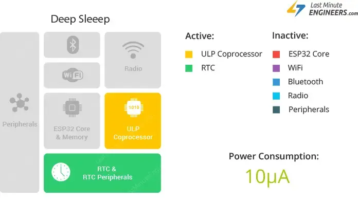
When the ESP32 enters deep sleep mode, the central processing units (CPUs), most of the RAM, and all digital peripherals are powered off. The only operational components of the chip are:
- Ultra-Low-Power (ULP) Coprocessor
- Real-Time Clock (RTC) Controller
- RTC Peripherals
- RTC fast and slow memory
Power consumption during deep sleep mode varies from approximately 0.15 mA (if the ULP coprocessor is active) to 10µA.
During deep sleep, the main CPU is inactive, while the ULP Coprocessor continues to function, monitoring sensors and awakening the CPU as needed. This mode, known as the ULP sensor-monitored pattern, is beneficial for applications requiring the CPU to respond to external events, timers, or a combination of both, while conserving power.
Furthermore, the main memory of the chip is disabled in deep sleep, resulting in the loss of stored data, which becomes inaccessible.
However, data stored in the RTC memory remains intact even during deep sleep, allowing retrieval after the chip wakes up. This feature is used to store Wi-Fi and Bluetooth connection data before entering deep sleep.
To preserve data after reboot, declare global variables with the RTC_DATA_ATTR attribute and store them in RTC memory. For example: RTC_DATA_ATTR int myVar = 0;
Upon awakening from deep sleep, the chip undergoes a reset and starts executing the program from the beginning.
Unlike other sleep modes, the system does not automatically enter deep sleep. Instead, the esp_deep_sleep_start() function is used to trigger deep sleep immediately after configuring wake-up sources.
ESP32 Deep Sleep Wake-up sources
The ESP32 can be roused from deep sleep mode by various sources, including:
- Timer
- Touch pad
- External wakeup (ext0 & ext1)
Multiple wake-up sources can be employed simultaneously, causing the chip to awaken when any of the specified sources is activated.
It’s crucial to note that it’s possible to place the ESP32 into deep sleep without defining any wake-up sources.
ESP32 Wake-up Source : Timer
The ESP32’s RTC controller is equipped with an internal timer feature that enables you to awaken the ESP32 after a specific duration.
This functionality is particularly beneficial for projects that involve time-sensitive tasks or daily routines while aiming to conserve power.
To set up the timer as a wake-up source, you can utilize the esp_sleep_enable_timer_wakeup(time_in_us) function, where you specify the desired duration in microseconds (μs).
Example Code
To grasp its functionality, let’s explore an example provided in the library. Open your Arduino IDE, navigate to File > Examples > ESP32 > Deep Sleep, and choose the TimerWakeUp sketch.
This sketch demonstrates a basic scenario of deep sleep utilizing a timer as the wake-up source, along with storing data in RTC memory for use after reboot.
#define uS_TO_S_FACTOR 1000000ULL  /* Conversion factor for micro seconds to seconds */
#define TIME_TO_SLEEP  5        /* Time ESP32 will go to sleep (in seconds) */

RTC_DATA_ATTR int bootCount = 0;

/*
Method to print the reason by which ESP32
has been awaken from sleep
*/
void print_wakeup_reason(){
  esp_sleep_wakeup_cause_t wakeup_reason;

  wakeup_reason = esp_sleep_get_wakeup_cause();

  switch(wakeup_reason)
  {
    case ESP_SLEEP_WAKEUP_EXT0 : Serial.println("Wakeup caused by external signal using RTC_IO"); break;
    case ESP_SLEEP_WAKEUP_EXT1 : Serial.println("Wakeup caused by external signal using RTC_CNTL"); break;
    case ESP_SLEEP_WAKEUP_TIMER : Serial.println("Wakeup caused by timer"); break;
    case ESP_SLEEP_WAKEUP_TOUCHPAD : Serial.println("Wakeup caused by touchpad"); break;
    case ESP_SLEEP_WAKEUP_ULP : Serial.println("Wakeup caused by ULP program"); break;
    default : Serial.printf("Wakeup was not caused by deep sleep: %d\n",wakeup_reason); break;
  }
}

void setup(){
  Serial.begin(115200);
  delay(1000); //Take some time to open up the Serial Monitor

  //Increment boot number and print it every reboot
  ++bootCount;
  Serial.println("Boot number: " + String(bootCount));

  //Print the wakeup reason for ESP32
  print_wakeup_reason();

  /*
  First we configure the wake up source
  We set our ESP32 to wake up every 5 seconds
  */
  esp_sleep_enable_timer_wakeup(TIME_TO_SLEEP * uS_TO_S_FACTOR);
  Serial.println("Setup ESP32 to sleep for every " + String(TIME_TO_SLEEP) +
  " Seconds");

  /*
  Next we decide what all peripherals to shut down/keep on
  By default, ESP32 will automatically power down the peripherals
  not needed by the wakeup source, but if you want to be a poweruser
  this is for you. Read in detail at the API docs
  http://esp-idf.readthedocs.io/en/latest/api-reference/system/deep_sleep.html
  Left the line commented as an example of how to configure peripherals.
  The line below turns off all RTC peripherals in deep sleep.
  */
  //esp_deep_sleep_pd_config(ESP_PD_DOMAIN_RTC_PERIPH, ESP_PD_OPTION_OFF);
  //Serial.println("Configured all RTC Peripherals to be powered down in sleep");

  /*
  Now that we have setup a wake cause and if needed setup the
  peripherals state in deep sleep, we can now start going to
  deep sleep.
  In the case that no wake up sources were provided but deep
  sleep was started, it will sleep forever unless hardware
  reset occurs.
  */
  Serial.println("Going to sleep now");
  Serial.flush();
  esp_deep_sleep_start();
  Serial.println("This will never be printed");
}

void loop(){
  //This is not going to be called
}
After uploading the sketch, open the serial monitor with a baud rate of 115200 bps.
The ESP32 will awaken every 5 seconds, displaying the wake-up reason and bootCount on the serial monitor, before returning to deep sleep.
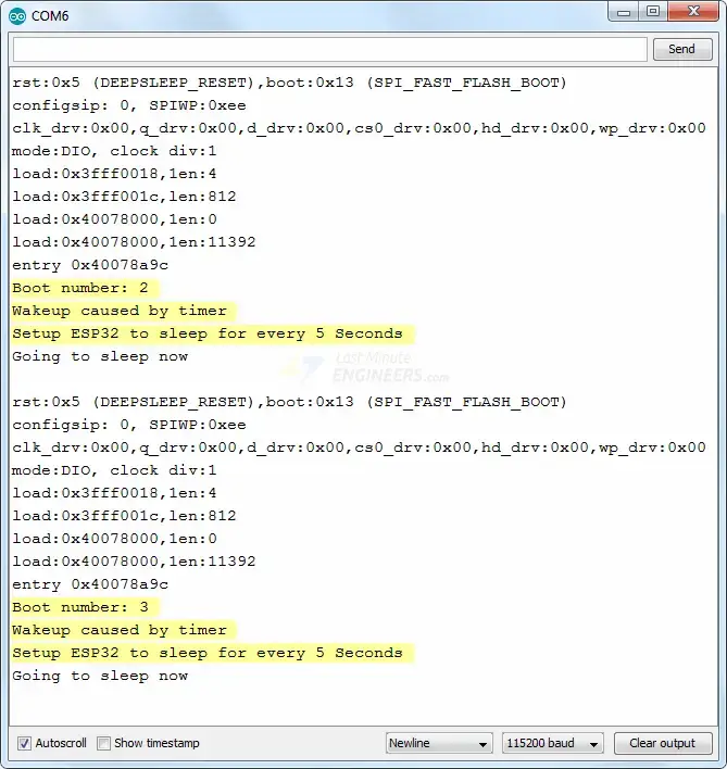
To test, reset the ESP32 by pressing the EN button; this action should reset the bootCount to 1, indicating the complete wiping of RTC memory.
Code Explanation:
The initial two lines of code establish the duration for which the ESP32 will remain in a sleep state.
In this instance, the conversion factor from microseconds to seconds is utilized, enabling the specification of the sleep time in seconds within the TIME_TO_SLEEP variable. Here, the ESP32 is set to enter deep sleep mode for 5 seconds.
#define uS_TO_S_FACTOR 1000000ULL  /* Conversion factor for micro seconds to seconds */
#define TIME_TO_SLEEP  5        /* Time ESP32 will go to sleep (in seconds) */
As mentioned earlier, data can be stored in the ESP32’s RTC memory (8kB SRAM), which remains intact during deep sleep but gets erased upon ESP32 reset.
To store data in RTC memory, simply prepend the RTC_DATA_ATTR attribute before defining a variable. In this example, the bootCount variable is designated to reside in RTC memory, tracking how many times the ESP32 has woken up from deep sleep.
RTC_DATA_ATTR int bootCount = 0;
Subsequently, the print_wakeup_reason() function is defined to report the reason for the ESP32’s awakening from deep sleep.
void print_wakeup_reason(){
  esp_sleep_wakeup_cause_t wakeup_reason;

  wakeup_reason = esp_sleep_get_wakeup_cause();

  switch(wakeup_reason)
  {
    case ESP_SLEEP_WAKEUP_EXT0 : Serial.println("Wakeup caused by external signal using RTC_IO"); break;
    case ESP_SLEEP_WAKEUP_EXT1 : Serial.println("Wakeup caused by external signal using RTC_CNTL"); break;
    case ESP_SLEEP_WAKEUP_TIMER : Serial.println("Wakeup caused by timer"); break;
    case ESP_SLEEP_WAKEUP_TOUCHPAD : Serial.println("Wakeup caused by touchpad"); break;
    case ESP_SLEEP_WAKEUP_ULP : Serial.println("Wakeup caused by ULP program"); break;
    default : Serial.printf("Wakeup was not caused by deep sleep: %d\n",wakeup_reason); break;
  }
}
In the setup function, serial communication with the PC is initialized.
Serial.begin(115200);
The bootCount variable is then incremented by one and displayed on the serial monitor, indicating the number of times the ESP32 has awakened from deep sleep.
++bootCount;
Serial.println("Boot number: " + String(bootCount));
Subsequently, the print_wakeup_reason() function is invoked, though any desired function can be called to perform a specific task, such as reading a sensor value.
print_wakeup_reason();
The timer wake-up source is configured using the esp_sleep_enable_timer_wakeup(time_in_us) function. Here, the ESP32 is programmed to awaken every 5 seconds.
esp_sleep_enable_timer_wakeup(TIME_TO_SLEEP * uS_TO_S_FACTOR);
Finally, the ESP32 is put to sleep by executing the esp_deep_sleep_start() function.
esp_deep_sleep_start();
In this sketch, the ESP32 enters deep sleep within the setup() function itself, bypassing the loop() function, which is consequently left empty.
void loop(){
  //This is not going to be called
}
ESP32 Wake-up Source : Touch Pad
You can wake the ESP32 from deep sleep mode using specific touch pins.
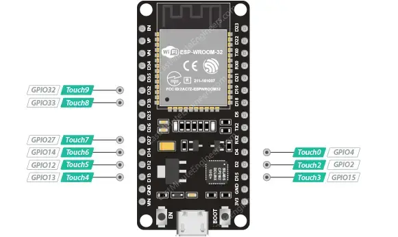
Enabling touch pin wake-up for the ESP32 is straightforward. In the Arduino IDE, you simply need to utilize the esp_sleep_enable_touchpad_wakeup() function.
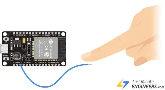
Wiring
Let’s connect a wire to GPIO#15 (Touch#3), which will serve as the touch wake-up source. You can attach any conductive object such as wire, aluminum foil, conductive cloth, or conductive paint to the touch-sensitive pin to turn it into a touchpad.
Example Code
To understand its operation, let’s examine an example from the library. Open your Arduino IDE, navigate to File > Examples > ESP32 > Deep Sleep, and open the TouchWakeUp sketch.
This sketch illustrates a basic deep sleep scenario with touch as the wake-up source and demonstrates how to store data in RTC memory for post-reboot use.
#define Threshold 40 /* Greater the value, more the sensitivity */

RTC_DATA_ATTR int bootCount = 0;
touch_pad_t touchPin;
/*
Method to print the reason by which ESP32
has been awaken from sleep
*/
void print_wakeup_reason(){
  esp_sleep_wakeup_cause_t wakeup_reason;

  wakeup_reason = esp_sleep_get_wakeup_cause();

  switch(wakeup_reason)
  {
    case ESP_SLEEP_WAKEUP_EXT0 : Serial.println("Wakeup caused by external signal using RTC_IO"); break;
    case ESP_SLEEP_WAKEUP_EXT1 : Serial.println("Wakeup caused by external signal using RTC_CNTL"); break;
    case ESP_SLEEP_WAKEUP_TIMER : Serial.println("Wakeup caused by timer"); break;
    case ESP_SLEEP_WAKEUP_TOUCHPAD : Serial.println("Wakeup caused by touchpad"); break;
    case ESP_SLEEP_WAKEUP_ULP : Serial.println("Wakeup caused by ULP program"); break;
    default : Serial.printf("Wakeup was not caused by deep sleep: %d\n",wakeup_reason); break;
  }
}

/*
Method to print the touchpad by which ESP32
has been awaken from sleep
*/
void print_wakeup_touchpad(){
  touchPin = esp_sleep_get_touchpad_wakeup_status();

  switch(touchPin)
  {
    case 0  : Serial.println("Touch detected on GPIO 4"); break;
    case 1  : Serial.println("Touch detected on GPIO 0"); break;
    case 2  : Serial.println("Touch detected on GPIO 2"); break;
    case 3  : Serial.println("Touch detected on GPIO 15"); break;
    case 4  : Serial.println("Touch detected on GPIO 13"); break;
    case 5  : Serial.println("Touch detected on GPIO 12"); break;
    case 6  : Serial.println("Touch detected on GPIO 14"); break;
    case 7  : Serial.println("Touch detected on GPIO 27"); break;
    case 8  : Serial.println("Touch detected on GPIO 33"); break;
    case 9  : Serial.println("Touch detected on GPIO 32"); break;
    default : Serial.println("Wakeup not by touchpad"); break;
  }
}

void callback(){
  //placeholder callback function
}

void setup(){
  Serial.begin(115200);
  delay(1000); //Take some time to open up the Serial Monitor

  //Increment boot number and print it every reboot
  ++bootCount;
  Serial.println("Boot number: " + String(bootCount));

  //Print the wakeup reason for ESP32 and touchpad too
  print_wakeup_reason();
  print_wakeup_touchpad();

  //Setup interrupt on Touch Pad 3 (GPIO15)
  touchAttachInterrupt(T3, callback, Threshold);

  //Configure Touchpad as wakeup source
  esp_sleep_enable_touchpad_wakeup();

  //Go to sleep now
  Serial.println("Going to sleep now");
  esp_deep_sleep_start();
  Serial.println("This will never be printed");
}

void loop(){
  //This will never be reached
}
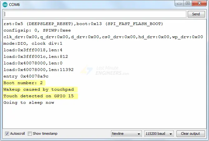
Once the sketch is uploaded, open the serial monitor and set the baud rate to 115200 bps.
Now, when the pin is touched, the ESP32 will display the boot count, wake-up reason, and which GPIO was touched on the serial monitor.
Code Explanation:
The initial line of code sets the threshold value for the touch pin to 40. Adjusting this value allows for sensitivity customization in accordance with your project requirements.
#define Threshold 40 /* Greater the value, more the sensitivity */
As previously mentioned, data can be stored in the ESP32’s RTC memory (8kB SRAM), which persists during deep sleep but gets erased upon ESP32 reset.
To store data in RTC memory, simply prefix the variable definition with the RTC_DATA_ATTR attribute. In this example, the bootCount variable keeps track of how many times the ESP32 has awakened from deep sleep.
RTC_DATA_ATTR int bootCount = 0;
Following this, a variable named touchPin of type touch_pad_t (an enum type) is defined. This variable aids in printing the GPIO by which the ESP32 was awakened from sleep.
touch_pad_t touchPin;
Next, the print_wakeup_reason() function is defined to print the reason for the ESP32 waking up from deep sleep.
void print_wakeup_reason(){
  esp_sleep_wakeup_cause_t wakeup_reason;

  wakeup_reason = esp_sleep_get_wakeup_cause();

  switch(wakeup_reason)
  {
    case ESP_SLEEP_WAKEUP_EXT0 : Serial.println("Wakeup caused by external signal using RTC_IO"); break;
    case ESP_SLEEP_WAKEUP_EXT1 : Serial.println("Wakeup caused by external signal using RTC_CNTL"); break;
    case ESP_SLEEP_WAKEUP_TIMER : Serial.println("Wakeup caused by timer"); break;
    case ESP_SLEEP_WAKEUP_TOUCHPAD : Serial.println("Wakeup caused by touchpad"); break;
    case ESP_SLEEP_WAKEUP_ULP : Serial.println("Wakeup caused by ULP program"); break;
    default : Serial.printf("Wakeup was not caused by deep sleep: %d\n",wakeup_reason); break;
  }
}
Additionally, the print_wakeup_touchpad() function is defined to print the GPIO number by which the ESP32 was awakened from deep sleep.
void print_wakeup_touchpad(){
  touchPin = esp_sleep_get_touchpad_wakeup_status();

  switch(touchPin)
  {
    case 0  : Serial.println("Touch detected on GPIO 4"); break;
    case 1  : Serial.println("Touch detected on GPIO 0"); break;
    case 2  : Serial.println("Touch detected on GPIO 2"); break;
    case 3  : Serial.println("Touch detected on GPIO 15"); break;
    case 4  : Serial.println("Touch detected on GPIO 13"); break;
    case 5  : Serial.println("Touch detected on GPIO 12"); break;
    case 6  : Serial.println("Touch detected on GPIO 14"); break;
    case 7  : Serial.println("Touch detected on GPIO 27"); break;
    case 8  : Serial.println("Touch detected on GPIO 33"); break;
    case 9  : Serial.println("Touch detected on GPIO 32"); break;
    default : Serial.println("Wakeup not by touchpad"); break;
  }
}
Furthermore, a callback() function is defined, serving as an Interrupt Service Routine (ISR) triggered every time a touch interrupt occurs. However, this function remains inactive if the ESP32 is in deep sleep, hence it’s left empty.
void callback(){
  //placeholder callback function
}
In the setup function, serial communication with the PC is initialized.
Serial.begin(115200);
The bootCount variable is then incremented by one and printed to the serial monitor to indicate the number of times the ESP32 has awakened from deep sleep.
++bootCount;
Serial.println("Boot number: " + String(bootCount));
Subsequently, the print_wakeup_reason() and print_wakeup_touchpad() functions are called. Alternatively, any desired function can be invoked to perform a specific task, such as reading the value of a sensor.
print_wakeup_reason();
print_wakeup_touchpad();
Next, the interrupt is attached to one of the touch pins with the desired sensitivity threshold. In this case, the interrupt is attached to touch pad 3 (GPIO15).
touchAttachInterrupt(T3, callback, Threshold);
Following this, the touch wake-up source is configured using the esp_sleep_enable_touchpad_wakeup() function.
esp_sleep_enable_touchpad_wakeup();
Finally, the ESP32 is put into deep sleep by calling the esp_deep_sleep_start() function.
esp_deep_sleep_start();
In this sketch, the ESP32 enters deep sleep within the setup() function itself, hence it never reaches the loop() function, which is consequently left blank.
void loop(){
  //This is not going to be called
}
ESP32 Wake-up Source : External Wake-up
There are two categories of external triggers to awaken the ESP32 from deep sleep:
- ext0 – Use this when you want to awaken the chip using a specific GPIO pin exclusively.
- ext1 – Use this when you want to awaken the chip using multiple GPIO pins.
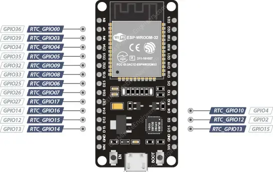
If you intend to utilize an interrupt pin to awaken the ESP32 from deep sleep, you must utilize the so-called RTC_GPIO pins. These GPIOs are linked to the RTC low-power subsystem, allowing their utilization when the ESP32 is in deep sleep.
The RTC_GPIO pins are:
ext0 External Wake-up Source
The ESP32 can be set up to awaken from deep sleep when one of the RTC_GPIO pins changes its logic level.
To enable this wake-up source, utilize the esp_sleep_enable_ext0_wakeup(GPIO_PIN, LOGIC_LEVEL) function. This function requires two parameters: the GPIO pin number and the desired logic level (LOW or HIGH) to trigger the wake-up.
Since ext0 utilizes RTC IO to wake up the ESP32, the RTC peripherals remain active during deep sleep.
Moreover, with the RTC IO module enabled, you can utilize the internal pullup or pulldown resistors. Configure them using the rtc_gpio_pullup_en() and rtc_gpio_pulldown_en() functions before calling esp_deep_sleep_start().
Wiring
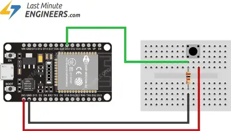
Connect a push button to GPIO#33 using a 10K pull-down resistor.
Example Code
To understand its operation, refer to the example provided in the library. Open your Arduino IDE, navigate to File > Examples > ESP32 > Deep Sleep, and open the ExternalWakeUp sketch.
This sketch illustrates a basic deep sleep example with ext0 as the wake-up source.
#define BUTTON_PIN_BITMASK 0x200000000 // 2^33 in hex

RTC_DATA_ATTR int bootCount = 0;

/*
Method to print the reason by which ESP32
has been awaken from sleep
*/
void print_wakeup_reason(){
  esp_sleep_wakeup_cause_t wakeup_reason;

  wakeup_reason = esp_sleep_get_wakeup_cause();

  switch(wakeup_reason)
  {
    case ESP_SLEEP_WAKEUP_EXT0 : Serial.println("Wakeup caused by external signal using RTC_IO"); break;
    case ESP_SLEEP_WAKEUP_EXT1 : Serial.println("Wakeup caused by external signal using RTC_CNTL"); break;
    case ESP_SLEEP_WAKEUP_TIMER : Serial.println("Wakeup caused by timer"); break;
    case ESP_SLEEP_WAKEUP_TOUCHPAD : Serial.println("Wakeup caused by touchpad"); break;
    case ESP_SLEEP_WAKEUP_ULP : Serial.println("Wakeup caused by ULP program"); break;
    default : Serial.printf("Wakeup was not caused by deep sleep: %d\n",wakeup_reason); break;
  }
}

void setup(){
  Serial.begin(115200);
  delay(1000); //Take some time to open up the Serial Monitor

  //Increment boot number and print it every reboot
  ++bootCount;
  Serial.println("Boot number: " + String(bootCount));

  //Print the wakeup reason for ESP32
  print_wakeup_reason();

  /*
  First we configure the wake up source
  We set our ESP32 to wake up for an external trigger.
  There are two types for ESP32, ext0 and ext1 .
  ext0 uses RTC_IO to wakeup thus requires RTC peripherals
  to be on while ext1 uses RTC Controller so doesnt need
  peripherals to be powered on.
  Note that using internal pullups/pulldowns also requires
  RTC peripherals to be turned on.
  */
  esp_sleep_enable_ext0_wakeup(GPIO_NUM_33,1); //1 = High, 0 = Low

  //If you were to use ext1, you would use it like
  //esp_sleep_enable_ext1_wakeup(BUTTON_PIN_BITMASK,ESP_EXT1_WAKEUP_ANY_HIGH);

  //Go to sleep now
  Serial.println("Going to sleep now");
  esp_deep_sleep_start();
  Serial.println("This will never be printed");
}

void loop(){
  //This is not going to be called
}
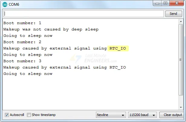
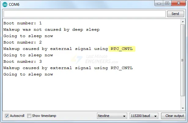
Once the sketch is uploaded, open your serial monitor and set the baud rate to 115200 bps.
Now, when you press the push button, the ESP32 will display the boot count and wake-up reason on the serial monitor. Press the button multiple times to observe the boot count increase with each press. Also, note that ext0 uses RTC IO to awaken the ESP32.
Code Explanation:
The first line of code defines a bitmask. It’s not necessary for ext0 external wake-up, so it can be disregarded for now. We will delve into its use in the explanation for ext1 external wake-up.
#define BUTTON_PIN_BITMASK 0x200000000 // 2^33 in hex
As mentioned earlier, you can store data in the ESP32’s RTC memory (8kB SRAM), which persists during deep sleep but gets erased upon reset. To store data in RTC memory, simply add the RTC_DATA_ATTR attribute before defining a variable. In this example, the bootCount variable is stored in RTC memory to track the number of times the ESP32 has woken up from deep sleep.
RTC_DATA_ATTR int bootCount = 0;
Next, the print_wakeup_reason() function is defined to print the reason why the ESP32 has been awakened from deep sleep.
void print_wakeup_reason(){
  esp_sleep_wakeup_cause_t wakeup_reason;

  wakeup_reason = esp_sleep_get_wakeup_cause();

  switch(wakeup_reason)
  {
    case ESP_SLEEP_WAKEUP_EXT0 : Serial.println("Wakeup caused by external signal using RTC_IO"); break;
    case ESP_SLEEP_WAKEUP_EXT1 : Serial.println("Wakeup caused by external signal using RTC_CNTL"); break;
    case ESP_SLEEP_WAKEUP_TIMER : Serial.println("Wakeup caused by timer"); break;
    case ESP_SLEEP_WAKEUP_TOUCHPAD : Serial.println("Wakeup caused by touchpad"); break;
    case ESP_SLEEP_WAKEUP_ULP : Serial.println("Wakeup caused by ULP program"); break;
    default : Serial.printf("Wakeup was not caused by deep sleep: %d\n",wakeup_reason); break;
  }
}
In the setup, the serial communication with the PC is initialized.
Serial.begin(115200);
The bootCount variable is then incremented by one and printed to the serial monitor to display the number of times the ESP32 has woken up from deep sleep.
++bootCount;
Serial.println("Boot number: " + String(bootCount));
Subsequently, the print_wakeup_reason() function is called to print the wake-up reason.
print_wakeup_reason();
Now, the ext0 external wake-up source is configured using the esp_sleep_enable_ext0_wakeup(GPIO_PIN, LOGIC_LEVEL) function. This function requires two parameters: the GPIO pin number and the logic level (LOW or HIGH) to trigger the wake-up. In this example, the ESP32 is set to wake up when the logic level of GPIO#33 becomes HIGH.
esp_sleep_enable_ext0_wakeup(GPIO_NUM_33,1);
Finally, the ESP32 is put into deep sleep by calling the esp_deep_sleep_start() function.
esp_deep_sleep_start();
In this sketch, the ESP32 enters deep sleep within the setup() function, so it never reaches the loop() function. Consequently, the loop() function is left empty.
void loop(){
  //This is not going to be called
}
ext1 External Wake-up Source
The ESP32 can be set up to awaken from deep sleep using multiple pins. It’s important to note that these pins must be among the RTC GPIO pins.
Since the ext1 wake-up source utilizes an RTC controller, it doesn’t necessitate RTC peripherals or RTC memory to be powered on. Consequently, internal pull-up and pull-down resistors are unavailable in this scenario.
To utilize the internal pull-up or pull-down resistors, we must ensure that the RTC peripherals remain active during sleep. We can then configure the pull-up/pull-down resistors using the rtc_gpio_pullup_en() and rtc_gpio_pulldown_en() functions before entering sleep.
The esp_sleep_enable_ext1_wakeup(BUTTON_PIN_MASK, LOGIC_LEVEL) function is employed to activate this wake-up source. This function requires two parameters. The first is a bit mask that specifies the pins we intend to use. The second parameter can be one of the two logic levels mentioned below to trigger the wake-up:
- Wake up if any selected pin is HIGH (
ESP_EXT1_WAKEUP_ANY_HIGH) - Wake up if all selected pins are LOW (
ESP_EXT1_WAKEUP_ALL_LOW)
Bitmask
Understanding the bitmask is easiest when represented in binary format. In this format, the bit numbering corresponds to the standard GPIO numbering. The least significant bit (LSB) represents GPIO#0, and the most significant bit (MSB) represents GPIO#39.
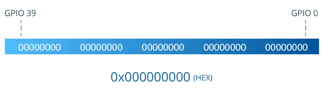
In the bitmask:
- 0 represents masked pins
- 1 represents pins enabled as a wake-up source
To enable a GPIO to wake up, you must set a 1 to its corresponding location and 0 to each of the remaining pins. Finally, the bitmask is converted to hexadecimal.
For instance, to use GPIO#32 and GPIO#33 as external wake-up sources, the bitmask would be:
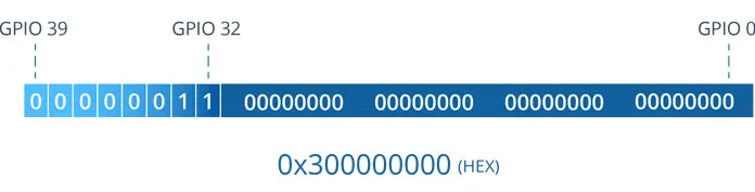
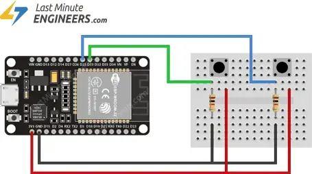
Wiring
Connect the two push buttons to GPIO#33 and GPIO#32 using 10K pull-down resistors.
Example Code
To demonstrate this, let’s use the ExternalWakeup example from the library. Open your Arduino IDE, navigate to File > Examples > ESP32 > Deep Sleep, and open the ExternalWakeup sketch.
Make three changes to the sketch:
- Change the BUTTON_PIN_BITMASK constant
- Comment out the code for ext0
- Uncomment the code for ext1
#define BUTTON_PIN_BITMASK 0x300000000

RTC_DATA_ATTR int bootCount = 0;

/*
Method to print the reason by which ESP32
has been awaken from sleep
*/
void print_wakeup_reason(){
  esp_sleep_wakeup_cause_t wakeup_reason;

  wakeup_reason = esp_sleep_get_wakeup_cause();

  switch(wakeup_reason)
  {
    case ESP_SLEEP_WAKEUP_EXT0 : Serial.println("Wakeup caused by external signal using RTC_IO"); break;
    case ESP_SLEEP_WAKEUP_EXT1 : Serial.println("Wakeup caused by external signal using RTC_CNTL"); break;
    case ESP_SLEEP_WAKEUP_TIMER : Serial.println("Wakeup caused by timer"); break;
    case ESP_SLEEP_WAKEUP_TOUCHPAD : Serial.println("Wakeup caused by touchpad"); break;
    case ESP_SLEEP_WAKEUP_ULP : Serial.println("Wakeup caused by ULP program"); break;
    default : Serial.printf("Wakeup was not caused by deep sleep: %d\n",wakeup_reason); break;
  }
}

void setup(){
  Serial.begin(115200);
  delay(1000); //Take some time to open up the Serial Monitor

  //Increment boot number and print it every reboot
  ++bootCount;
  Serial.println("Boot number: " + String(bootCount));

  //Print the wakeup reason for ESP32
  print_wakeup_reason();

  /*
  First we configure the wake up source
  We set our ESP32 to wake up for an external trigger.
  There are two types for ESP32, ext0 and ext1 .
  ext0 uses RTC_IO to wakeup thus requires RTC peripherals
  to be on while ext1 uses RTC Controller so doesnt need
  peripherals to be powered on.
  Note that using internal pullups/pulldowns also requires
  RTC peripherals to be turned on.
  */
  //esp_sleep_enable_ext0_wakeup(GPIO_NUM_33,1); //1 = High, 0 = Low

  //If you were to use ext1, you would use it like
  esp_sleep_enable_ext1_wakeup(BUTTON_PIN_BITMASK,ESP_EXT1_WAKEUP_ANY_HIGH);

  //Go to sleep now
  Serial.println("Going to sleep now");
  esp_deep_sleep_start();
  Serial.println("This will never be printed");
}

void loop(){
  //This is not going to be called
}
Once uploaded, open your serial monitor with the baud rate set to 115200 bps. When you press the push button, you will receive similar information on the serial monitor. Additionally, note that ext1 uses the RTC controller to wake up the ESP32.
Code Explanation:
This code is almost identical to the code for ext0, with just two modifications.
Firstly, at the start of the code, a bit mask is defined. In this example, we’re using pins GPIO#32 and GPIO#33, so the mask has 1’s at their respective positions, with 32 0’s on the right and 6 0’s on the left.
00000011 00000000 00000000 00000000 00000000 BIN = 0x300000000 HEX
#define BUTTON_PIN_BITMASK 0x300000000
Secondly, ext1 is enabled as the wake-up source.
esp_sleep_enable_ext1_wakeup(BUTTON_PIN_BITMASK,ESP_EXT1_WAKEUP_ANY_HIGH);
Related article
- ESP32 Fundamentals: Delving Into Hall Effect Sensor Technology
- Mastering Bluetooth Low Energy with ESP32 (BLE)
- Understanding ESP32 Sleep Modes for Optimal Power Usage
- Simplified ESP32 OTA Setup: Arduino IDE Web Updater Tutorial
- Unlocking ESP32 Potential: Easy OTA Programming Tutorial


