

If you’re new to robotics and looking for an easier way to control motors, the L298N motor driver is a great option. It allows you to control the speed and direction of two DC motors with ease.
Furthermore, the L298N motor driver arduino can also handle a bipolar stepper motor like the NEMA 17. If you’re interested in learning more about using this motor driver, you can check out the tutorial provided. It will provide you with valuable information and guidance.
Controlling a DC Motor
To have precise control over a DC motor, we need to be able to adjust its speed and spinning direction. This can be achieved by combining two techniques: PWM and H-Bridge.
PWM (Pulse Width Modulation) – Controlling Speed
The speed of a DC motor can be controlled by manipulating its input voltage. PWM is a commonly used technique for this purpose. It involves sending a series of ON-OFF pulses, where the average voltage is adjusted by changing the width of the pulses, known as the Duty Cycle. A higher duty cycle results in a higher average voltage, increasing the motor speed. Conversely, a lower duty cycle decreases the average voltage, reducing the motor speed.

H-Bridge – Controlling Spinning Direction
The spinning direction of a DC motor can be controlled by changing the polarity of its input voltage. An H-Bridge circuit is commonly employed to achieve this. It consists of four switches arranged in an “H” shape, with the motor placed in the center. By closing specific switches simultaneously, the polarity of the voltage applied to the motor is reversed, causing a change in the spinning direction.
The animation below illustrates the functioning of an H-Bridge circuit.

L298N Motor Driver Chip
The L298N is a powerful motor driver chip commonly used for controlling DC motors. It features two integrated H-bridges, making it suitable for driving a pair of DC motors simultaneously. With a supply range of 5V to 35V, it can handle a wide range of voltage inputs.
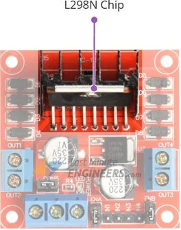
Each channel of the L298N arduino is capable of delivering a continuous current of up to 2A, making it well-suited for various motor applications. The chip is often equipped with a heat sink to dissipate heat generated during operation.
Its versatility and high current handling capacity make the L298N an excellent choice for motor control in robotics, automation, and other projects.
Technical Specifications
Here are the specifications:
| Motor output voltage | 5V – 35V |
| Motor output voltage (Recommended) | 7V – 12V |
| Logic input voltage | 5V – 7V |
| Continuous current per channel | 2A |
| Max Power Dissipation | 25W |
For more details, please refer below datasheet.
L298N Motor Driver Module Pinout
The L298N motor driver module features 11 pins that facilitate its connectivity with external components. Let’s explore each pin individually.

Power Pins
The module receives power through a 3-pin screw terminal with a 3.5mm pitch.
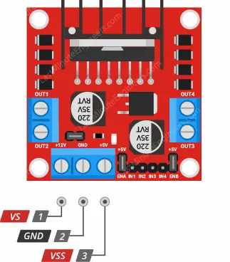
- VS: This pin supplies power to the internal H-Bridge of the L298N module, which drives the connected motors. It accepts input voltages ranging from 5V to 12V.
- VSS: Used to power the logic circuitry within the L298N IC, this pin can be supplied with voltages between 5V and 7V.
- GND: This pin serves as the common ground connection.
Output Pins
The L298N motor driver arduino provides output channels for two motors: OUT1 and OUT2 for motor A, and OUT3 and OUT4 for motor B. These channels are accessible through two 3.5mm-pitch screw terminals located at the edge of the module. You can connect two 5-12V DC motors to these terminals.

Each channel on the module is capable of supplying up to 2A of current to the DC motor, depending on the capacity of the motor’s power supply.
Direction Control Pins
The direction control pins allow you to specify the rotation direction of each motor. These pins directly control the switches in the H-Bridge circuit of the L298N chip.
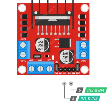
- IN1 and IN2: These pins determine the spinning direction of motor A.
- IN3 and IN4: These pins control the spinning direction of motor B.
To control the motor’s spinning direction, apply a logic HIGH (5V) or logic LOW (Ground) signal to these inputs. The provided chart illustrates the different combinations and their corresponding outcomes.
| Input1 | Input2 | Spinning Direction |
| Low(0) | Low(0) | Motor OFF |
| High(1) | Low(0) | Forward |
| Low(0) | High(1) | Backward |
| High(1) | High(1) | Motor OFF |
Speed Control Pins
The speed control pins, ENA and ENB, are used to enable or disable the motors and regulate their speed.

- Pulling these pins HIGH initiates motor rotation, while pulling them LOW stops the motors. However, by utilizing Pulse Width Modulation (PWM), you can control the motors’ speed.
Typically, the module comes with jumpers on these pins. When the jumpers are in place, the motors spin at full speed. To programmatically control the motor speed, remove the jumpers and connect the pins to Arduino’s PWM-enabled pins.
On-board 5V Regulator and Jumper
The L298N module features an on-board 5V regulator and a jumper that controls its operation.

With the jumper in place, the 5V regulator is enabled, and the logic power supply (VSS) is derived from the motor power supply (VS). In this configuration, the 5V input terminal functions as an output pin, providing a stable 5V with a maximum current of 0.5A. This output can be used to power devices such as an Arduino or other circuits that require 5V.
If the jumper is removed, the 5V regulator is disabled, and a separate 5V power supply must be connected to the VSS pin.
If the motor power supply voltage is less than 12V, the jumper can be left in place. However, if the motor power supply voltage exceeds 12V, the jumper must be removed to prevent damage to the on-board 5V regulator. It is also crucial to avoid supplying power to both the VSS and VS pins simultaneously when the jumper is connected.
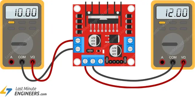
Voltage Drop of L298N
The L298N motor driver module experiences a voltage drop of approximately 2 volts when operating. This voltage drop is due to the internal switching transistors, which have a forward-biased voltage drop of around 1 volt each. Since an H-bridge configuration, like the one in the L298N arduino, requires the current to pass through two transistors, the total voltage drop becomes 2 volts.
As a result, when you provide a certain voltage at the input of the L298N, the output voltage that reaches the connected motor will be reduced by approximately 2 volts. For example, if you supply 12 volts to the L298N, the motors will receive around 10 volts.
This voltage drop can impact the performance of the connected motors. To achieve the maximum speed and performance, it’s important to take the voltage drop into account when selecting the power supply for your motors. For instance, if you have 5V motors, you may need to provide around 7 volts at the input of the L298N arduino to compensate for the 2V voltage drop.
Additionally, the voltage drop leads to power dissipation in the L298N, generating heat during operation. To manage this heat effectively and prevent overheating, it’s advisable to use a proper heatsink with the L298N motor driver module, especially when driving motors with higher current requirements.
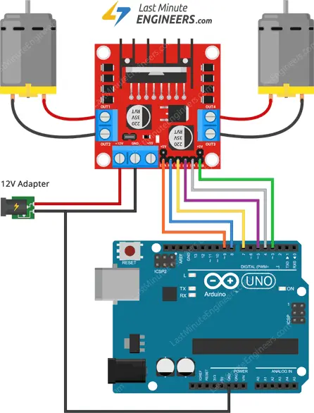
Wiring an L298N Motor Driver Module to an Arduino
To connect the L298N motor driver module to an Arduino, follow these steps:
Power Supply: Connect an external power supply with a voltage range of 5V to 35V to the VS and GND terminals on the L298N module. This power supply will drive the motors, so ensure it is appropriate for your motors’ voltage requirements.
Logic Power Supply: Keep the 5V-EN jumper in place to enable the on-board 5V regulator. The logic circuitry of the L298N module will be powered by this 5V supply, which is derived from the motor power supply (VS).
Enable Pins: Connect the ENA and ENB pins of the L298N module to two digital output pins on the Arduino. These pins control the motors’ enable signal and can be used to turn the motors on/off.
Input Pins: Connect the IN1, IN2, IN3, and IN4 pins of the L298N module to four digital output pins on the Arduino. These pins control the direction of rotation for each motor.
Motor Connections: Connect one motor to terminals A (OUT1 and OUT2) and the other motor to terminals B (OUT3 and OUT4) on the L298N module. The polarity of the motor connections determines the direction of rotation, so ensure they are wired correctly.
Optional: If you wish to control the motor speed using PWM, connect the ENA and ENB pins to PWM-enabled digital output pins on the Arduino.
After making these connections, you can program the Arduino to control the L298N module and drive the connected motors. Remember to double-check your connections and voltage requirements to avoid any damage to the motors or the L298N module.
Parts Required
| Component Name | Buy Now |
| Arduino Uno REV3 | Amazon |
| L298N Motor Driver controller Board Module Stepper Motor DC Dual H-Bridge for Arduino | Amazon |
| Geared Motor DC3V-12V DC for Four-wheel Drive Toy Car | Amazon |
| Breadboard | Amazon |
| BOJACK 1000 Pcs 25 Values Resistor Kit 1 Ohm-1M Ohm with 5% 1/4W | Amazon |
Arduino Example Code – Speed and Direction Control with L298N Motor Driver
The following sketch demonstrates how to effectively control the speed and spinning direction of a DC motor using the L298N Motor Driver Arduino. This code serves as a foundation for more practical experiments and projects involving motor control.
The sketch executes a one-revolution movement in one direction and then reverses the motor’s spinning direction. It incorporates acceleration and deceleration for smoother control.
// Motor A connections
int enA = 9;
int in1 = 8;
int in2 = 7;
// Motor B connections
int enB = 3;
int in3 = 5;
int in4 = 4;

void setup() {
	// Set all the motor control pins to outputs
	pinMode(enA, OUTPUT);
	pinMode(enB, OUTPUT);
	pinMode(in1, OUTPUT);
	pinMode(in2, OUTPUT);
	pinMode(in3, OUTPUT);
	pinMode(in4, OUTPUT);

	// Turn off motors - Initial state
	digitalWrite(in1, LOW);
	digitalWrite(in2, LOW);
	digitalWrite(in3, LOW);
	digitalWrite(in4, LOW);
}

void loop() {
	directionControl();
	delay(1000);
	speedControl();
	delay(1000);
}

// This function lets you control spinning direction of motors
void directionControl() {
	// Set motors to maximum speed
	// For PWM maximum possible values are 0 to 255
	analogWrite(enA, 255);
	analogWrite(enB, 255);

	// Turn on motor A & B
	digitalWrite(in1, HIGH);
	digitalWrite(in2, LOW);
	digitalWrite(in3, HIGH);
	digitalWrite(in4, LOW);
	delay(2000);

	// Now change motor directions
	digitalWrite(in1, LOW);
	digitalWrite(in2, HIGH);
	digitalWrite(in3, LOW);
	digitalWrite(in4, HIGH);
	delay(2000);

	// Turn off motors
	digitalWrite(in1, LOW);
	digitalWrite(in2, LOW);
	digitalWrite(in3, LOW);
	digitalWrite(in4, LOW);
}

// This function lets you control speed of the motors
void speedControl() {
	// Turn on motors
	digitalWrite(in1, LOW);
	digitalWrite(in2, HIGH);
	digitalWrite(in3, LOW);
	digitalWrite(in4, HIGH);

	// Accelerate from zero to maximum speed
	for (int i = 0; i < 256; i++) {
		analogWrite(enA, i);
		analogWrite(enB, i);
		delay(20);
	}

	// Decelerate from maximum speed to zero
	for (int i = 255; i >= 0; --i) {
		analogWrite(enA, i);
		analogWrite(enB, i);
		delay(20);
	}

	// Now turn off motors
	digitalWrite(in1, LOW);
	digitalWrite(in2, LOW);
	digitalWrite(in3, LOW);
	digitalWrite(in4, LOW);
}
This code allows you to experiment with the motor control by changing the spinning direction and adjusting the speed. You can further build upon this foundation to create more complex motor control applications.
Code Explanation:
Sure! Let’s break down the code step by step:
// Motor A connections
int enA = 9;
int in1 = 8;
int in2 = 7;
// Motor B connections
int enB = 3;
int in3 = 5;
int in4 = 4;
This section of the code defines the pin connections between the Arduino and the L298N Motor Driver Arduino. It assigns the pins for enabling and controlling the direction of two motors (Motor A and Motor B).
void setup() {
	// Set all the motor control pins to outputs
	pinMode(enA, OUTPUT);
	pinMode(enB, OUTPUT);
	pinMode(in1, OUTPUT);
	pinMode(in2, OUTPUT);
	pinMode(in3, OUTPUT);
	pinMode(in4, OUTPUT);

	// Turn off motors - Initial state
	digitalWrite(in1, LOW);
	digitalWrite(in2, LOW);
	digitalWrite(in3, LOW);
	digitalWrite(in4, LOW);
}
In the setup function, all the motor control pins are initialized as outputs using the pinMode function. Additionally, all the input pins (IN1, IN2, IN3, and IN4) are set to LOW, ensuring that the motors start in a stationary state.
void loop() {
	directionControl();
	delay(1000);
	speedControl();
	delay(1000);
}
In the loop function, the code calls two functions, directionControl() and speedControl(), which are responsible for controlling the motor’s direction and speed, respectively. After each function is executed, there is a delay of 1000 milliseconds (1 second) before proceeding to the next function call.
void directionControl() {
    // Set motors to maximum speed
    // For PWM, maximum possible values are 0 to 255
    analogWrite(enA, 255);
    analogWrite(enB, 255);

    // Turn on motor A & B (forwards)
    digitalWrite(in1, HIGH);
    digitalWrite(in2, LOW);
    digitalWrite(in3, HIGH);
    digitalWrite(in4, LOW);
    delay(2000);

    // Change motor directions (reverse)
    digitalWrite(in1, LOW);
    digitalWrite(in2, HIGH);
    digitalWrite(in3, LOW);
    digitalWrite(in4, HIGH);
    delay(2000);

    // Turn off motors
    digitalWrite(in1, LOW);
    digitalWrite(in2, LOW);
    digitalWrite(in3, LOW);
    digitalWrite(in4, LOW);
}
The directionControl() function handles the spinning direction of the motors. It first sets the enable pins (enA and enB) to 255, which means the motors will run at maximum speed using PWM (pulse-width modulation). Then, it sets the input pins (in1, in2, in3, and in4) to move Motor A and Motor B forwards (one revolution) for 2 seconds.
After 2 seconds, the input pins are set to reverse the spinning direction of both motors. Motor A moves backwards (reverse) while Motor B also moves in reverse. This reversal is again done for 2 seconds.
Finally, all the input pins are set to LOW, turning off the motors.
void speedControl() {
    // Turn on motors (forwards)
    digitalWrite(in1, LOW);
    digitalWrite(in2, HIGH);
    digitalWrite(in3, LOW);
    digitalWrite(in4, HIGH);

    // Accelerate from zero to maximum speed
    for (int i = 0; i < 256; i++) {
        analogWrite(enA, i);
        analogWrite(enB, i);
        delay(20);
    }

    // Decelerate from maximum speed to zero
    for (int i = 255; i >= 0; --i) {
        analogWrite(enA, i);
        analogWrite(enB, i);
        delay(20);
    }

    // Turn off motors
    digitalWrite(in1, LOW);
    digitalWrite(in2, LOW);
    digitalWrite(in3, LOW);
    digitalWrite(in4, LOW);
}
The speedControl() function is responsible for controlling the speed of the motors. It first sets the input pins to move both motors forwards.
Then, the function uses a for loop to gradually increase the PWM value from 0 to 255, accelerating the motors. The delay of 20 milliseconds between each increment creates the effect of acceleration.
Next, the loop reverses, and the PWM values decrease from 255 to 0, decelerating the motors smoothly. Again, the delay of 20 milliseconds between each decrement creates the deceleration effect.
Finally, all the input pins are set to LOW, turning off the motors.
Overall, this code demonstrates how to control the direction and speed of DC motors using the L298N Motor Driver and Arduino, providing a foundation for further motor control applications.
Related article
- Servo Motor Basics: How It Works and Arduino Interface Guide
- Stepper Motor Control with Arduino: L298N Motor Driver Interface
- Step-by-Step Guide: Arduino Stepper Motor Control with A4988 Driver
- Step-by-Step Guide: Arduino Stepper Motor Control with DRV8825 Driver
- Arduino Motor Control: DRV8833 Motor Driver for DC Motors
- Arduino Motor Control: L293D Motor Driver for DC Motors
- Step-by-Step Guide: L293D Stepper Motor Driver with Arduino


