
A simple and cost-effective method to incorporate temperature sensing into your Arduino project is by utilizing the TMP36 Temperature Sensor. These sensors offer good precision and require no additional components to function. With just a few connections and some Arduino code, you can start sensing temperature quickly!
Parts Required
| Component Name | Buy Now |
| Arduino Uno REV3 | Amazon |
| TMP36 Temperature Sensor | Amazon |
| I2C TWI 1602 Serial LCD Module Display | Amazon |
| Breadboards Kit | Amazon |
TMP36 Temperature Sensor
The TMP36, crafted by Analog Devices, is a precision centigrade temperature sensor operating at low voltage. It produces a voltage output directly proportional to the temperature in degrees Celsius, making it exceptionally compatible with Arduino projects.
This sensor boasts remarkable precision, enduring performance, and versatility across various environmental conditions. Remarkably, it operates without the need for supplementary components. Moreover, calibration isn’t necessary, and it maintains a typical accuracy of ±1°C at 25°C, with a deviation of ±2°C across temperatures ranging from -40°C to +125°C.
Operating within a power supply range of 2.7V to 5.5V, the TMP36 consumes a mere 50µA during active temperature conversions, ensuring minimal self-heating (below 0.1°C in stagnant air). Furthermore, it features a shutdown function that reduces supply current to less than 0.5µA.
Below are the comprehensive specifications:
| Power supply | 2.7V to 5.5V |
| Current draw | 50µA |
| Temperature range | -40°C to 125°C |
| Accuracy | ±2°C |
| Output scale factor | 10mV/°C |
| Output range | 0.1V (-40°C) to 1.75V (125°C) |
| Output at 25°C | 750mV |
For more information, please refer below datasheet.
Working Principle
The TMP36 operates on a solid-state method for temperature measurement. It capitalizes on the principle that the voltage drop across the base and emitter (known as forward voltage – Vbe) of the Diode-connected transistor decreases at a consistent rate with temperature rise. Through precise amplification of this voltage alteration, an analog signal directly correlating to temperature is effortlessly generated.
The linear correlation between forward voltage and temperature is why diode-connected transistors serve as effective temperature measurement tools. Essentially, this method forms the basis of temperature measurement, though there have been advancements in the technique over time. Further details on this approach can be explored here.
The advantageous aspect is that all intricate calculations are internally handled within the TMP36. It simply produces a voltage output that linearly corresponds to temperature.
Temperature Measurement Procedure
Utilizing the TMP36 is straightforward. Simply connect the left pin to a power source (within the range of 2.7-5.5V) and the right pin to ground (assuming the sensor’s flat side is oriented towards you). Subsequently, the middle pin will yield an analog voltage directly proportional (linearly) to the temperature in degrees Celsius. This correlation is readily observable in the voltage versus temperature characteristic. Notably, the analog output voltage remains unaffected by variations in the power supply.
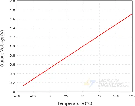
Converting the voltage to temperature involves employing the basic formula:
Temperature (°C) = (Vout – 0.5) * 100
For instance, if the output voltage is 1V, the temperature is calculated as (1 – 0.5) * 100 = 50 °C.
Before determining the temperature reading, we subtract 0.5V from the output voltage due to the TMP36’s 500mV offset, which enables it to measure negative temperatures. Then, to convert this voltage into temperature, we simply multiply by 100, reflecting the TMP36’s scaling factor of 10mV per degree Celsius. As simple as ABC.
Testing the TMP36 Sensor
Assessing the TMP36 is relatively straightforward. To begin, connect the left pin to a power source ranging from 2.7V to 5.5V (such as two AA batteries), and the right pin to the ground (ensuring the sensor’s flat side is facing towards you). Then, connect your multimeter in DC voltage mode to the ground and the middle pin. Under standard room temperature conditions (25°C), the voltage reading should stabilize around 0.75V.
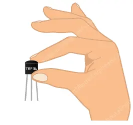
Experiment by gently exerting pressure on the plastic casing of the sensor to observe a temperature increase.
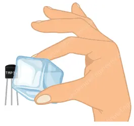
Alternatively, test by touching the sensor with an ice cube (placed in a plastic bag to prevent water from contacting your circuit) and observe the temperature decrease.
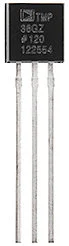
TMP36 Sensor Pinout
The TMP36 is available in three distinct form factors, with the most prevalent being the 3-pin TO-92 package, resembling a transistor. Here’s an overview of its pinout:
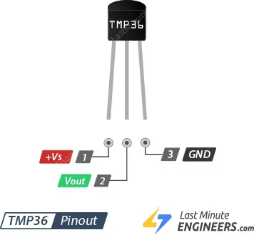
+Vs: This pin serves as the power supply for the sensor, accommodating voltages ranging from 2.7V to 5.5V.
Vout: This pin generates an analog voltage that linearly correlates with the temperature. It should be linked to an Analog (ADC) input.
GND: This pin serves as the ground connection.
Connecting the TMP36 Temperature Sensor to an Arduino
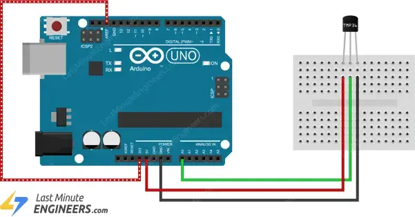
The process of linking the TMP36 to an Arduino is remarkably simple. You’ll only need to establish connections for three pins: two for power and one for reading the sensor’s value.
The sensor can be powered from either a 3.3V or 5V output. Connect the positive voltage to the ‘+Vs’ pin, and ground should be connected to ‘GND’. The middle pin, ‘Vout’, functions as the analog signal output from the sensor and should be linked to the A0 analog input of the Arduino.
Below is the setup for conducting experiments with the TMP36:
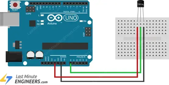
To measure air temperature, place the sensor in open air or attach it to an object whose temperature you wish to monitor, such as a heat sink.
Interpreting Analog Temperature Data
As depicted in the above wiring diagram, the TMP36’s output is linked to one of the Arduino’s analog inputs. The value of this analog input can be retrieved using the analogRead() function.
However, the analogRead() function doesn’t directly provide the sensor’s output voltage. Instead, it maps the input voltage between 0 and the ADC reference voltage (typically the operating voltage, either 5V or 3.3V unless modified) to 10-bit integer values ranging from 0 to 1023. To revert this value to the sensor’s output voltage, employ this formula:
Vout = (reading from ADC) * (5 / 1024)
This equation converts the ADC’s 0-1023 reading into a 0-5V range.
For users employing a 3.3V Arduino, the formula becomes:
Vout = (reading from ADC) * (3.3 / 1024)
This calculation translates the ADC’s 0-1023 reading into a 0-3.3V range.
Subsequently, to convert volts into temperature, employ this formula:
Temperature (°C) = (Vout – 0.5) * 100
Arduino Code – Basic Thermometer
The provided sketch offers a swift method to retrieve data from a TMP36 temperature sensor, serving as a foundation for further experimentation and project development. It straightforwardly captures the TMP36 value via analog port A0 and displays the current temperature (in both °C and °F) on the serial monitor. Feel free to upload it to your Arduino.
// Define the analog pin, the TMP36's Vout pin is connected to
#define sensorPin A0

void setup() {
  // Begin serial communication at 9600 baud rate
  Serial.begin(9600);
}

void loop() {
  // Get the voltage reading from the TMP36
  int reading = analogRead(sensorPin);

  // Convert that reading into voltage
  // Replace 5.0 with 3.3, if you are using a 3.3V Arduino
  float voltage = reading * (5.0 / 1024.0);

  // Convert the voltage into the temperature in Celsius
  float temperatureC = (voltage - 0.5) * 100;

  // Print the temperature in Celsius
  Serial.print("Temperature: ");
  Serial.print(temperatureC);
  Serial.print("\xC2\xB0"); // shows degree symbol
  Serial.print("C  |  ");

  // Print the temperature in Fahrenheit
  float temperatureF = (temperatureC * 9.0 / 5.0) + 32.0;
  Serial.print(temperatureF);
  Serial.print("\xC2\xB0"); // shows degree symbol
  Serial.println("F");

  delay(1000); // wait a second between readings
}
You should see the following output in the serial monitor.
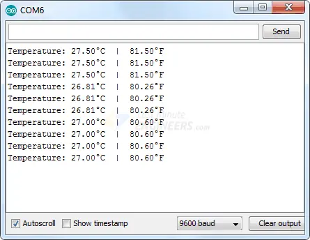
Code Explanation:
The sketch begins by defining the Arduino pin connected to the sensor’s Vout pin.
#define sensorPin A0
In the setup function, we initialize the serial connection with the computer.
void setup() {
  Serial.begin(9600);
}
Within the loop, we first read the analog signal from the TMP36 using the analogRead() function.
int reading = analogRead(sensorPin);
Then, we employ the formulas discussed earlier to convert the analog reading into voltage and subsequently into temperature.
float voltage = reading * (5.0 / 1024.0);

float temperatureC = (voltage - 0.5) * 100;
The obtained results are then printed on the Serial Monitor.
Serial.print("Temperature: ");
Serial.print(temperatureC);
Serial.print("\xC2\xB0"); // shows degree symbol
Serial.print("C  |  ");
The temperature value obtained is in Celsius (°C). We convert it to Fahrenheit (°F) using a straightforward formula and display it on the Serial Monitor.
T(°F) = T(°C) × 9/5 + 32
float temperatureF = (temperatureC * 9.0 / 5.0) + 32.0;
Serial.print(temperatureF);
Serial.print("\xC2\xB0"); // shows degree symbol
Serial.println("F");
Enhancing the Accuracy of the TMP36 Sensor
Since we haven’t configured the reference voltage (ARef) for analog input (the default analog reference on 5V Arduino boards is 5 volts), the maximum resolution from the ADC is 5/1024 = 4.88 mV or 0.49°C.
For improved precision, utilizing the 3.3V reference voltage as ARef instead of the 5V option will yield more accurate and less noisy results. With 3.3V as the reference voltage, the resolution becomes 3.3/1024 = 3.22 mV or 0.32°C.
To utilize the 3.3V pin as the analog reference, connect it to the AREF (Analog Reference) input as follows:
Additionally, certain changes are required in the code. The lines needing modification or addition are highlighted below:
// Define the analog pin, the TMP36's Vout pin is connected to
#define sensorPin A0

// Tie ARef to 3.3V
#define aref_voltage 3.3
void setup() {
  // Begin serial communication at 9600 baud rate
  Serial.begin(9600);

  // If you want to set the aref to something other than 5v
  analogReference(EXTERNAL);}

void loop() {
  // Get the voltage reading from the TMP36
  int reading = analogRead(sensorPin);

  // Convert that reading into voltage
  float voltage = reading * (aref_voltage / 1024.0);
  // Convert the voltage into the temperature in Celsius
  float temperatureC = (voltage - 0.5) * 100;

  // Print the temperature in Celsius
  Serial.print("Temperature: ");
  Serial.print(temperatureC);
  Serial.print("\xC2\xB0"); // shows degree symbol
  Serial.print("C  |  ");

  // Print the temperature in Fahrenheit
  float temperatureF = (temperatureC * 9.0 / 5.0) + 32.0;
  Serial.print(temperatureF);
  Serial.print("\xC2\xB0"); // shows degree symbol
  Serial.println("F");

  delay(1000); // wait a second between readings
}
You should observe the following output in the serial monitor.
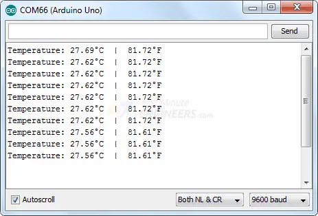
This adjustment provides a slight enhancement in accuracy, but for many projects, this may still be insufficient.
An alternative to the TMP36 is employing a digital temperature sensor like the DS18B20, which shares the same package. Digital temperature sensors offer superior noise immunity, especially beneficial when placed at a distance or in electrically noisy environments.
Arduino Project – Standalone Thermometer with TMP36 and an I2C LCD
Occasionally, you may conceive an idea where displaying real-time temperature readings and issuing alerts when the temperature exceeds specified thresholds is necessary. In such cases, utilizing a 16×2 character LCD instead of a serial monitor becomes advantageous.
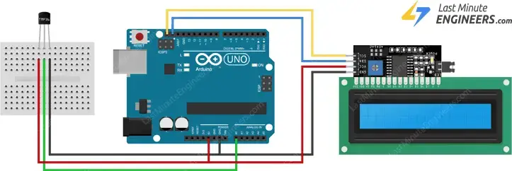
In this instance, we’ll connect an I2C LCD to the Arduino alongside the TMP36.
Connecting the I2C LCD is straightforward, as depicted in the wiring diagram below. If you’re unfamiliar with 16×2 character I2C LCDs, it’s advisable to peruse the tutorial provided.
The following diagram illustrates the wiring setup.
The ensuing sketch will display temperature values on the 16×2 character I2C LCD. The code closely resembles the initial example, albeit with values printed on the I2C LCD.
// Include the LiquidCrystal_I2C library
#include <LiquidCrystal_I2C.h>
// Create a new instance of the LiquidCrystal_I2C class
LiquidCrystal_I2C lcd(0x3F, 16, 2);
// Define a custom degree character
byte Degree[] = {
B00111,
B00101,
B00111,
B00000,
B00000,
B00000,
B00000,
B00000
};
// Define the analog pin, the TMP36's Vout pin is connected to
#define sensorPin A0
void setup() {
// Start the LCD and turn on the backlight
lcd.init();
lcd.backlight();
// Create a custom character
lcd.createChar(0, Degree);
}
void loop() {
// Get the voltage reading from the TMP36
int reading = analogRead(sensorPin);
// Convert that reading into voltage
// Replace 5.0 with 3.3, if you are using a 3.3V Arduino
float voltage = reading * (5.0 / 1024.0);
// Convert the voltage into the temperature in Celsius
float temperatureC = (voltage - 0.5) * 100;
// Print the temperature on the LCD;
lcd.setCursor(0, 0);
lcd.print("Temperature:");
lcd.setCursor(0, 1);
lcd.print(temperatureC, 1);
lcd.write(0); // print the custom degree character
lcd.print("C ");
// Print the temperature in Fahrenheit
float temperatureF = (temperatureC * 9.0 / 5.0) + 32.0;
lcd.print(temperatureF, 1);
lcd.write(0); // print the custom degree character
lcd.print("F ");
delay(1000); // wait a second between readings
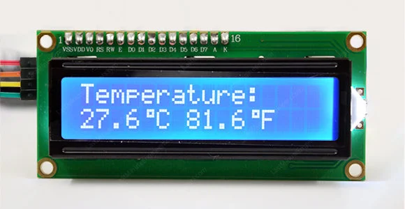
}
You should observe the following output on the LCD screen:
Related article
- Arduino LCD Tutorial: How to Interface a 16×2 Character LCD Module
- Step-by-Step Guide: LM35 Temperature Sensor Interfacing with Arduino
- Arduino DHT11 Sensor Tutorial: How to Interface and Read Data
- DHT11/DHT22 Interface with ESP8266 NodeMCU Web Server: Step-by-Step


