
In this guide, we will walk you through the process of interfacing a 4×4 keypad with an Arduino UNO. This step-by-step tutorial will provide you with detailed instructions on connecting and programming the keypad, making it easy for you to incorporate this versatile input device into your Arduino projects. Whether you’re a beginner or an experienced Arduino enthusiast, this guide will help you efficiently set up and use a 4×4 keypad with your Arduino UNO.
Overview of 4×4 Matrix Keypad
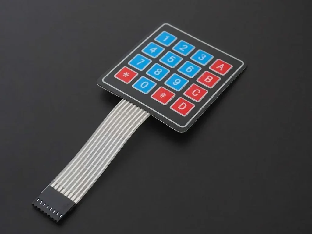
A keypad serves as an input device that detects and processes user key presses.
A 4×4 keypad arduino is structured with 4 rows and 4 columns, with switches positioned at the intersections.
When a key is pressed, it connects the corresponding row and column where the switch is located.
For additional details on the keypad and its usage, see the 4×4 Keypad topic in the sensors and modules section.
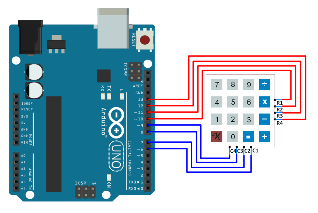
Connection Diagram of 4×4 Keypad with Arduino UNO
Reading a 4×4 Keypad with Arduino Uno
Learn how to read key presses from a 4×4 keypad and display them on the Arduino serial terminal.
We’ll use the Keypad library by Mark Stanley and Alexander Brevig for this task.
- Download the Library: Obtain the library from here.
- Install the Library: Extract the library and add it to the libraries folder in your Arduino IDE. For detailed instructions on adding a custom library to the Arduino IDE and using examples, refer to “Adding Library to Arduino IDE” in the Basics section.
- Import the Library: Find more information on the Keypad library and how to import it directly into the Arduino IDE here.
- Load the Example Sketch: Once the library is added, open the Arduino IDE and load the “CustomKeypad” example sketch from the newly added library.
In the “Custom Keypad” example sketch, digital pins 0 and 1 are used for connecting rows. This can cause issues for some users because:
The Arduino Uno uses digital pins 0 and 1 for Tx and Rx (serial communication).
Since the sketch relies on serial communication to display the key presses, using these pins can lead to errors.
Solution:
To avoid this, use pins other than 0 and 1. Refer to the sketch below for guidance:
byte rowPins[ROWS] = {R1, R2, R3, R4}; // Connect to the row pinouts of the keypad
byte colPins[COLS] = {C1, C2, C3, C4}; // Connect to the column pinouts of the keypad
Ensure the pins are connected as specified. Incorrect connections will result in incorrect key press detection.
4×4 Keypad Code for Arduino Uno
#include <Keypad.h>

const byte ROWS = 4; /* four rows */
const byte COLS = 4; /* four columns */
/* define the symbols on the buttons of the keypads */
char hexaKeys[ROWS][COLS] = {
  {'0','1','2','3'},
  {'4','5','6','7'},
  {'8','9','A','B'},
  {'C','D','E','F'}
};
byte rowPins[ROWS] = {10, 11, 12, 13}; /* connect to the row pinouts of the keypad */
byte colPins[COLS] = {6, 7, 8, 9}; /* connect to the column pinouts of the keypad */

/* initialize an instance of class NewKeypad */
Keypad customKeypad = Keypad( makeKeymap(hexaKeys), rowPins, colPins, ROWS, COLS);

void setup(){
Serial.begin(9600);
}

void loop(){
  char customKey = customKeypad.getKey();

  if (customKey){
Serial.println(customKey);
  }
}
Functions Used
1. makeKeymap(keys)
- Initializes the internal keymap to match the user-defined keymap.
2. Keypad customKeypad = Keypad( makeKeymap(keys), rowPins, colPins, rows, cols)
- Creates an object
customKeypadof the Keypad class and initializes it. rowPinsandcolPinsare the Arduino pins connected to the keypad’s rows and columns.rowsandcolsspecify the number of rows and columns on the keypad.
3. customKeypad.getKey()
- Identifies which key is pressed on the keypad.
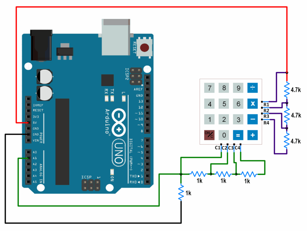
1-Wire interfacing of Keypad With Arduino
The previously described interfacing method uses 8 GPIO pins of the Arduino board. However, by utilizing the 1-wire interfacing method, we can achieve the same functionality using only 1 GPIO pin.
This technique employs a simple voltage divider to create distinct voltages for each key press.
Here’s how to connect a keypad to an Arduino using a single GPIO pin.
Connection Diagram of 1-Wire Keypad Interface With Arduino
Parts Required
| Component Name | Buy Now |
| Arduino Uno REV3 | Amazon |
| 4×4 Matrix Array Membrane Switch Keypad Keyboard 16 | Amazon |
One Wire Keypad Code for Arduino Uno
void setup() {
  Serial.begin(9600);	/* Define baud rate for serial communication */
}

void loop() {
  int adc_val;
  adc_val = analogRead(A1);	/* Read input from keypad */
  if (adc_val>850)
  {
    Serial.print("Key Pressed : ");
    Serial.println("0");
    delay(100);
  }
  else if ( adc_val>450  && adc_val<510)
  {
    Serial.print("Key Pressed : ");
    Serial.println("1");
    delay(100);
  }
  else if ( adc_val>300  && adc_val<350)
  {
    Serial.print("Key Pressed : ");
    Serial.println("2");
    delay(100);
  }
  else if ( adc_val>230  && adc_val<270)
  {
    Serial.print("Key Pressed : ");
    Serial.println("3");
    delay(100);
  }
  else if ( adc_val>160  && adc_val<180)
  {
    Serial.print("Key Pressed : ");
    Serial.println("4");
    delay(100);
  }
  else if ( adc_val>145  && adc_val<155)
  {
    Serial.print("Key Pressed : ");
    Serial.println("5");
    delay(100);
  }
  else if ( adc_val>125  && adc_val<135)
  {
    Serial.print("Key Pressed : ");
    Serial.println("6");
    delay(100);
  }
  else if ( adc_val>105  && adc_val<120)
  {
    Serial.print("Key Pressed : ");
    Serial.println("7");
    delay(100);
  }
  else if ( adc_val>92  && adc_val<99)
  {
    Serial.print("Key Pressed : ");
    Serial.println("8");
    delay(100);
  }
  else if ( adc_val>82  && adc_val<90)
  {
    Serial.print("Key Pressed : ");
    Serial.println("9");
    delay(100);
  }
  else if ( adc_val>77  && adc_val<81)
  {
    Serial.print("Key Pressed : ");
    Serial.println("A");
    delay(100);
  }
  else if ( adc_val>72  && adc_val<76)
  {
    Serial.print("Key Pressed : ");
    Serial.println("B");
    delay(100);
  }
  else if ( adc_val>63  && adc_val<68)
  {
    Serial.print("Key Pressed : ");
    Serial.println("C");
    delay(100);
  }
  else if ( adc_val>60  && adc_val<62)
  {
    Serial.print("Key Pressed : ");
    Serial.println("D");
    delay(100);
  }
  else if ( adc_val>57  && adc_val<59)
  {
    Serial.print("Key Pressed : ");
    Serial.println("E");
    delay(100);
  }
  else if( adc_val>52  && adc_val<56)
  {
    Serial.print("Key Pressed : ");
    Serial.println("F");
    delay(100);
  }
  else
  {

  }
  delay(100);
}
The ADC values used to detect key presses were determined experimentally. You may need to determine these values yourself based on your specific setup. The provided ADC values correspond to the resistor configuration shown in the interfacing diagram. Using different resistor values will result in incorrect outputs from the provided code. If you opt for different resistor values, you’ll need to experimentally determine the ADC values for each key press and update the code accordingly.
Related article
- Interface a 2-Axis Joystick with Arduino: A Processing Tutorial
- Control SMS & Calls with Arduino and A6 GSM Module
- Arduino and GPS: How to Interface NEO-6M Module
- 433MHz RF Tx-Rx Modules: Arduino Interface and Operation Explained


