

Within this tutorial, you will acquire the skills needed to manage a stepper motor using the ESP8266 NodeMCU board. Our approach entails employing the 28BYJ-48 unipolar stepper motor coupled with the ULN2003 motor driver. The programming aspect involves harnessing the Arduino IDE to interact with the ESP8266 board.
Parts Required
Introducing Stepper Motors
A stepper motor represents a brushless DC electric motor that segments a complete rotation into discrete steps. With each step being of identical magnitude, the motor advances one step at a time. This precise movement allows for the motor to be rotated by a specific angle, achieving a precise position. The stepper motor’s rotation can occur in either a clockwise or counterclockwise direction.
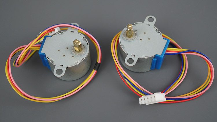
The accompanying image showcases a pair of 28BYJ-48 stepper motors.
Stepper motors encompass internal coils that induce stepwise motion of the motor shaft in either direction when electric current is applied to the coils in a defined manner.
Two variants of stepper motors exist: unipolar and bipolar stepper motors.
In this article, we won’t delve into the intricate details of how stepper motors are constructed and their internal operations. For an in-depth understanding of their functioning and the distinctions between the different types of stepper motors, we recommend perusing the article provided by the DroneBotWorkshop blog.
Overview of the 28BYJ-48 Stepper Motor
Stepper motors come with various specifications tailored to their unique functionalities. This guide centers around the widely employed 28BYJ-48 unipolar stepper motor, paired harmoniously with the ULN2003 motor driver.
Prominent Features of the 28BYJ-48 Stepper Motor
For a comprehensive grasp of the stepper motor’s defining attributes, consult the datasheet:
- Rated voltage: 5V DC
- Number of phases: 4
- Speed variation ratio: 1/64
- Stride angle: 5.625º/64
- Frequency: 100Hz
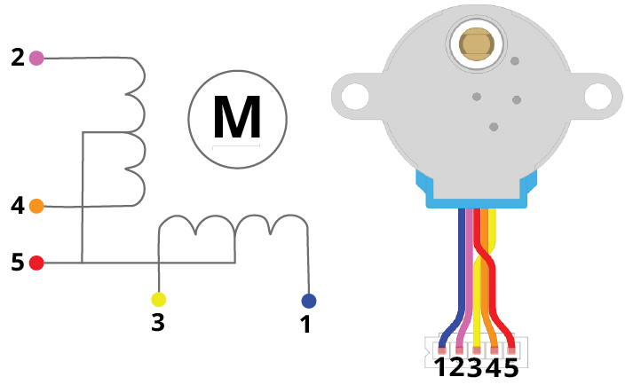
The 28BYJ-48 stepper motor comprises four coils in total. These coils are linked at one end to the motor’s red wire, connected to a 5V source. The opposite ends of these coils correspond to wires tinted in blue, pink, yellow, and orange. Activating the coils sequentially generates a step-by-step motion of the motor in either direction.
In half-step mode, the 28BYJ-48 Stepper Motor upholds a stride angle of 5.625°/64. This translates to the requirement of 64 steps (360º/5.625º = 64 steps) to complete a full revolution in half-step mode. When operating in full-step mode, this count decreases to 32 steps, resulting in one complete rotation.
However, an integral gear ratio of 64:1 influences the output shaft. This implies that for every 64 revolutions executed by the internal motor, the external shaft accomplishes a single revolution. Consequently, the motor must execute 32×64 = 2048 steps to realize a full rotation of the external shaft. This level of precision corresponds to a step angle of 360º/2048 steps = 0.18º/step.
To sum up:
- Total steps per revolution = 2048 steps
- Step angle = 0.18º/step
If you’re utilizing a distinct stepper motor, we recommend consulting the pertinent datasheet for a comprehensive understanding.
ULN2003 Motor Driver
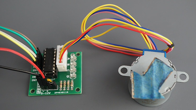
To establish a connection between the ESP8266 NodeMCU board and the stepper motor, we will employ the ULN2003 motor driver, depicted in the diagram below. Notably, the 28BYJ-48 stepper motor is frequently bundled with the ULN2003 motor driver.
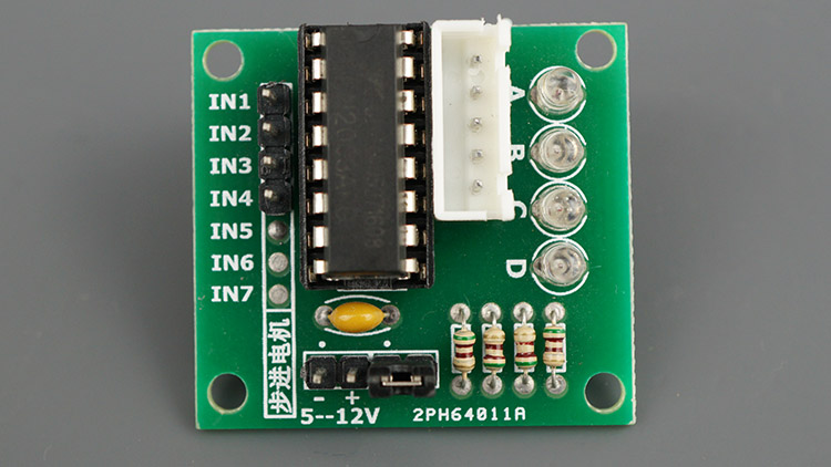
This module features a convenient connector that simplifies the process of linking the motor to the module. The module incorporates four input pins dedicated to controlling the coils responsible for the stepper motor’s motion. Additionally, the inclusion of four LEDs offers a visual representation of the coils’ operational status.
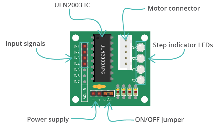
The module includes pins designated for connecting VCC and GND, alongside a jumper cap that functions as an ON/OFF switch for powering the stepper motor. Removing the jumper effectively cuts off power supply to the motor. For those desiring manual control, these pins can serve as connections for a physical switch.
ULN2003 Motor Driver Pinout
The following table shows the module pinout:
| IN1 | Control the motor: connect to a microcontroller digital pin |
| IN2 | Control the motor: connect to a microcontroller digital pin |
| IN3 | Control the motor: connect to a microcontroller digital pin |
| IN4 | Control the motor: connect to a microcontroller digital pin |
| VCC | Powers the motor |
| GND | Common GND |
| Motor connector | Connect the motor connector |
Wire Stepper Motor to the ESP8266 Board
This section outlines the steps to connect the stepper motor to the ESP8266 using the ULN2003 motor driver.
To achieve this, we will link IN1, IN2, IN3, and IN4 to GPIO pins 5, 4, 14, and 12 respectively. If needed, you have the flexibility to choose other appropriate digital pins by referring to our ESP8266 pinout reference guide.
For a clearer understanding of the process, please refer to the schematic diagram provided below.

| Motor Driver | ESP8266 |
| IN1 | GPIO 5 |
| IN2 | GPIO 4 |
| IN3 | GPIO 14 |
| IN4 | GPIO 12 |
Installing the AccelStepper Library
To effectively control stepper motors using a microcontroller, we will employ the AccelStepper library. This library serves as a valuable tool for our purpose of controlling the stepper motor with the ESP8266. It simplifies tasks such as defining the motor’s movement in terms of steps, setting speed and acceleration parameters, and more.
The library is well-documented, offering clear explanations of its various methods. You can access the detailed documentation here.
To integrate the AccelStepper library into your Arduino IDE, proceed with the following steps:
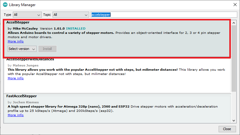
- Open the Arduino IDE and navigate to Sketch > Include Library > Manage Libraries…
- In the Library Manager, search for “accelstepper”.
- Locate and install the AccelStepper library developed by Mike McCauley. We will be using version 1.61.0 for this purpose.
Controlling the Stepper Motor with ESP8266 – Code
To implement stepper motor control using the ESP8266, copy the following code into your Arduino IDE. This example demonstrates continuous clockwise and counterclockwise rotations of the motor.
#include <AccelStepper.h>

const int stepsPerRevolution = 2048;  // change this to fit the number of steps per revolution

// ULN2003 Motor Driver Pins
#define IN1 5
#define IN2 4
#define IN3 14
#define IN4 12

// initialize the stepper library
AccelStepper stepper(AccelStepper::HALF4WIRE, IN1, IN3, IN2, IN4);

void setup() {
  // initialize the serial port
  Serial.begin(115200);

  // set the speed and acceleration
  stepper.setMaxSpeed(500);
  stepper.setAcceleration(100);
  // set target position
  stepper.moveTo(stepsPerRevolution);
}

void loop() {
  // check current stepper motor position to invert direction
  if (stepper.distanceToGo() == 0){
    stepper.moveTo(-stepper.currentPosition());
    Serial.println("Changing direction");
  }
  // move the stepper motor (one step at a time)
  stepper.run();
}
This code example was adapted from the library’s provided samples (File > Examples > AccelStepper > Bounce).
How the Code Works
To comprehend the functioning of the code, follow these steps:
#include <AccelStepper.h>
Determine the steps per revolution for your stepper motor; in this instance, it is set to 2048 steps:
const int stepsPerRevolution = 2048; // change this to fit the number of steps per revolution
Define the input pins for the motor. In this example, we’re using GPIOs 5, 4, 14, and 12, but feel free to select other appropriate GPIOs:
#define IN1 5
#define IN2 4
#define IN3 14
#define IN4 12
Create an instance of the AccelStepper library named stepper. Use the arguments AccelStepper::HALF4WIRE to indicate a four-wire stepper motor configuration, and the specified input pins. For the 28BYJ-48 stepper motor, the pin order is IN1, IN3, IN2, IN4, although this might differ for your motor.
AccelStepper stepper(AccelStepper::HALF4WIRE, IN1, IN3, IN2, IN4);
Within the setup() section, initialize the Serial Monitor with a baud rate of 115200.
Serial.begin(115200);
Set the maximum speed of the stepper motor using the setMaxSpeed() method, providing the desired speed in steps per second:
stepper.setMaxSpeed(500);
Use the setAcceleration() method to specify the acceleration, measured in steps per second per second:
stepper.setAcceleration(100);
Employ the moveTo() method to establish a target position. The run() function will then attempt to advance the motor towards the target position set by the latest call to this function. In this case, the target position is set to 2048, corresponding to a complete revolution for this motor:
stepper.moveTo(stepsPerRevolution);
In the loop(), the code will orchestrate clockwise and counterclockwise rotations of the stepper motor.
First, assess if the motor has attained its target position. You can accomplish this by using the distanceToGo() function, which measures the steps between the current and target positions. When the motor reaches the target position, the distanceToGo() function yields 0, triggering the following if statement:
if (stepper.distanceToGo() == 0){
Once the motor achieves the target position, a new target position is assigned. This new position mirrors the current position but in the opposite direction:
stepper.moveTo(-stepper.currentPosition());
Lastly, invoke the stepper.run() method to incrementally move the motor one step at a time within the loop().
stepper.run();
In essence, the run() method efficiently orchestrates the motor’s motion. It triggers stepping as necessary to attain the target position while considering acceleration and deceleration factors. For optimal performance, ensure frequent calls to run()—ideally within your main loop—while noting that each invocation advances the motor by at most one step based on the present speed and time elapsed since the previous step.
Demonstration
Load the code onto your board and execute the upload process. Once uploaded, the motor will continuously execute a clockwise rotation followed by a counterclockwise rotation. The rotational motion commences at a lower speed and gradually accelerates until attaining the intended speed just prior to reaching the target position.
For a visual illustration, you can view a brief video demonstration:
Conclusion
This tutorial served as an introductory guide to working with stepper motors using the ESP8266. Stepper motors enable precise movement by taking one step at a time, allowing accurate positioning of the motor shaft to specific angles.
In an upcoming tutorial, we will delve into creating a web server for remote control of the stepper motor using the ESP8266. Be sure to keep an eye out for that.
We trust that you have found this tutorial beneficial and informative.
Learn more about the ESP8266 with our resources:
- Step-by-Step Tutorial: Installing ESP8266 Board in Arduino IDE
- Complete ESP8266 Pinout Reference: Simplify Your Hardware Connections
- Mastering ESP8266 GPIO Interrupts: Arduino IDE Configuration Tips
- Complete Guide: ESP8266 Over The Air (OTA) Programming with Arduino IDE


