
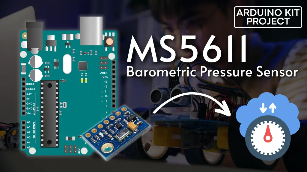
If you’re interested in determining the altitude of your RC aircraft, the elevation of the mountain pass you’re traversing, or the peak reached during your recent hiking adventure with friends, the affordable MS5611 barometric pressure sensor/altimeter could be the solution you’re looking for.
Parts Required
Hardware Overview
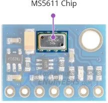
The module is centered around a compact, high-speed, accurate, energy-efficient, and low-noise barometric pressure sensor manufactured by MEAS Switzerland – the MS5611.
Capable of measuring barometric pressure within the range of 10 mbar to 1200 mbar, the MS5611 boasts an absolute accuracy of ±1.5 mbar between 450 to 1100 mbar. Beyond this range, the accuracy remains within ±2.5 mbar.
Primarily designed for altimeters and variometers, this sensor provides an altitude resolution of 0.012 mbar, equivalent to approximately 10cm (4 inches) of altitude.
Additionally, the MS5611 incorporates an on-chip temperature sensor to compensate for environmental changes and calibrate measurements. This temperature sensor offers reasonable precision, measuring ‘die temperature’ within the range of -40˚C to +85˚C with an accuracy of ±0.8˚C.
Power Requirement
Equipped with a MIC5205 3.3V precision voltage regulator and voltage level translator, this module offers compatibility with both 3.3V and 5V microcontrollers, ensuring seamless integration with your preferred setup.
The MS5611 operates with minimal power consumption, drawing less than 1.4mA during measurements and less than 0.15µA in standby mode. This efficiency makes it suitable for use in battery-operated devices such as handheld devices, wearables, or smartwatches.
Digital interfaces
Communication with the MS5611 can be facilitated via either I2C or SPI. The operational interface is determined by the state of the PS (Protocol Select) pin.
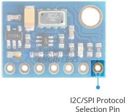
Setting the PS pin to LOW activates the SPI interface, while setting it to HIGH activates the I2C interface. By default, the module is configured for the I2C interface, thanks to the presence of a 1K pull-up resistor on the PS pin.
I2C Interface
For Arduino communication, the sensor utilizes the I2C interface, supporting two distinct I2C addresses: 0x77Hex and 0x76Hex. This flexibility enables the use of two MS5611 modules on the same bus or prevents address conflicts with other devices.
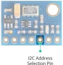
The CSB pin determines the I2C address, featuring a built-in 2.2K pull-down resistor. When left unconnected, the default I2C address is 0x77Hex; connecting it to VCC pulls the line HIGH, setting the I2C address to 0x76Hex.
SPI Interface
The sensor also supports SPI communication. To activate the SPI interface, simply connect the PS (Protocol Select) pin to ground.
Technical Specifications
Here are the complete specifications:
| Power supply | 3.3V to 5.5V |
| Current draw | ~1.4mA (during measurements) |
| ~0.15µA (during standby mode) | |
| Pressure Measurement Range | 10 to 1200 mbar |
| Pressure Absolute Accuracy | ±1.5 mbar |
| ADC Resolution | 24 bit |
| Temperature Range | -40˚C to +85˚C |
| Temperature Accuracy | ±0.8˚C |
For more details, please refer below datasheet.
MS5611 Module Pinout
Let’s examine the pinout of the MS5611 module.

Power Pins:
- VCC: This is the power pin, connected to the 5V output of your Arduino.
- GND: Common ground for power and logic.
SPI Logic pins:
- SCL: SPI Clock input pin.
- SDA: Serial Data In (MOSI) pin, transmitting data from your microcontroller to the MS5611.
- CSB: Chip Select pin. If multiple MS5611 modules are connected to one microcontroller, they can share SDA, SDO, and SCL pins, each assigned a unique CSB pin.
- SDO: Serial Data Out (MISO) pin, sending data from the MS5611 to your microcontroller.
- PS: Protocol Select pin. Pulling it LOW enables SPI communication.
I2C Logic pins:
- SCL: Also serves as the I2C clock pin, connected to your microcontroller’s I2C clock line.
- SDA: Also serves as the I2C data pin, connected to your microcontroller’s I2C data line.
- CSB pin determines the I2C address of the module. Leaving CSB unconnected defaults to an I2C address of 0x77Hex; connecting it to VCC sets the address to 0x76Hex.
- PS: Protocol Select pin. Leave it unconnected to enable I2C communication.
Connecting an MS5611 Module to an Arduino
Now that we have a comprehensive understanding of the module, we can proceed to connect it to our Arduino!
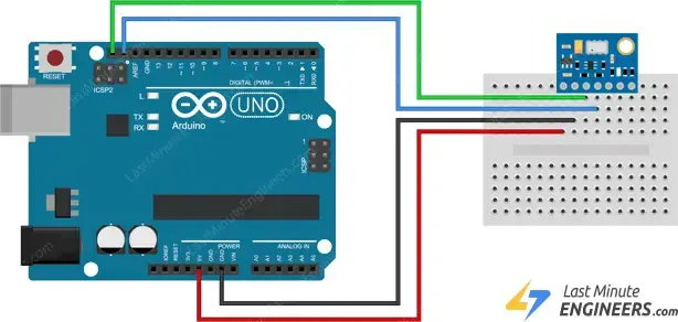
To begin, attach the VCC pin to the power supply, ensuring it’s within the range of 3V to 5V. Match this voltage with the logic level of your microcontroller. Typically, most Arduinos operate at 5V, while 3.3V logic devices require a 3.3V supply. Next, link the GND pin to the common ground.
Connect the SCL pin to the I2C clock pin and the SDA pin to the I2C data pin on your Arduino. Note that different Arduino boards have distinct I2C pins, so make sure to connect them accordingly. In Arduino boards with the R3 layout, the SDA (data line) and SCL (clock line) are located near the AREF pin on the pin headers, identified as A4 (SDA) and A5 (SCL).
Refer to the following diagram for the wiring setup.
Once the module is properly connected to the Arduino, it’s time to start coding!
Library Installation
To start accessing sensor data, you’ll need to install the MS5611 library, which can be found in the Arduino library manager.
To install the library, go to Sketch > Include Library > Manage Libraries… and wait for the Library Manager to update the list of available libraries.
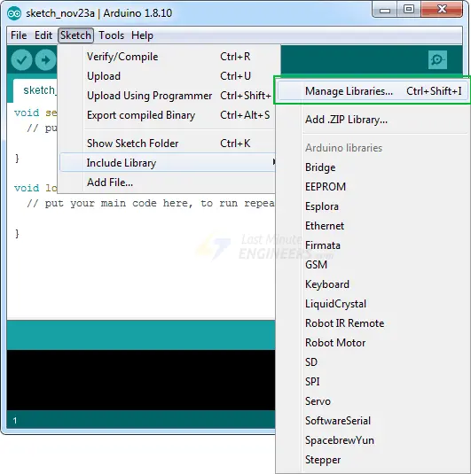
Filter your search by typing ‘ms5611’ and proceed to install the library.

Rob Tillart has also developed MS5611_SPI, an experimental SPI version of the library intended for communication with the MS5611 via the SPI interface. However, it has been observed that selecting SPI as the protocol may cause internal heating issues, resulting in inaccurate temperature readings. For this reason, our tutorial will solely focus on the I2C interface.
Arduino Code – Reading Pressure and Temperature
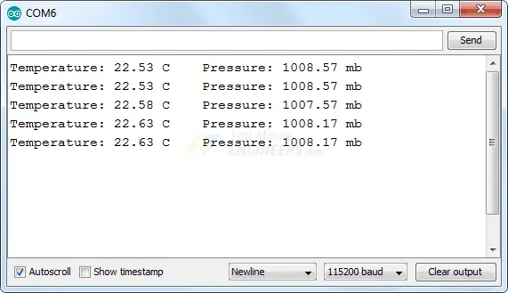
Below is a basic Arduino sketch. Upload it to your Arduino board, and you’ll observe pressure and temperature readings on the serial monitor.
#include "MS5611.h"

MS5611 MS5611(0x77);

void setup() {
  Serial.begin(115200);
  while(!Serial);

  if (!MS5611.begin()) {
    Serial.println("MS5611 not found, check wiring!");
    while (1);
  }
}

void loop() {
  MS5611.read();
  Serial.print("Temperature: ");
  Serial.print(MS5611.getTemperature(), 2);
  Serial.print("\tPressure: ");
  Serial.print(MS5611.getPressure(), 2);
  Serial.println();
  delay(1000);
}
Please note that you must set your serial monitor to a baud rate of 115200 to effectively run the sketch.
As you monitor the serial output, you’ll observe fluctuating data corresponding to changes in pressure and temperature. Experiment by moving the sensor around and observe how the data responds.
Code Explanation:
The code is fairly straightforward. It begins by including the MS5611.h library and creating a global object named MS5611 with an I2C address parameter of 0x77.
#include <Wire.h>

MS5611 MS5611(0x77);
In the setup function, serial communication with the PC is initialized, and the begin() function of MS5611 is called.
The MS5611.begin() function initializes the I2C interface, verifies the chip ID, performs a soft-reset, and waits for the sensor to calibrate after waking up.
void setup() {
  Serial.begin(115200);
  while(!Serial);

  if (!MS5611.begin()) {
    Serial.println("MS5611 not found, check wiring!");
    while (1);
  }
}
In the loop function, the MS5611.read() function is called to perform a sensor reading. Subsequently, the object’s (MS5611) methods are accessed using the dot operator.
- MS5611.getTemperature() returns the temperature reading.
- MS5611.getPressure() returns the barometric pressure reading.
void loop() {
  MS5611.read();
  Serial.print("Temperature: ");
  Serial.print(MS5611.getTemperature(), 2);
  Serial.print("\tPressure: ");
  Serial.print(MS5611.getPressure(), 2);
  Serial.println();
  delay(1000);
}
Related article
- Step-by-Step: Interfacing Multiple DS18B20 Sensors with Arduino
- MLX90614 Integration Guide for Arduino Temperature Sensing
- Arduino DHT11 Sensor Tutorial: How to Interface and Read Data
- Arduino DHT11 and DHT22 Sensor Interface: Step-by-Step Guide
- MAX6675 Thermocouple Module: Seamless Integration with Arduino
- Arduino-Compatible HTU21D Sensor: Monitor Temp & Humidity Easily


