
In your upcoming project, you may need to use your Arduino to control a high-voltage device, such as a lamp, fan, or household appliance. However, the Arduino, operating at 5 volts, cannot directly control these high-voltage appliances.
To address this issue, 2 relay module come into play. These self-contained modules are affordable, easy to connect, and ideal for DIY projects that require switching moderate amounts of AC or DC power. The only drawback is that, being electro-mechanical devices, they are more susceptible to wear and tear over time.
This tutorial will guide you through the process of setting up the relay module to control a lamp or another device. But before that, let’s have a quick introduction to relays.
How Do Relays Work?
At the core of a relay is an electromagnet, which is a wire coil that becomes a temporary magnet when electricity passes through it. The working principle of a relay can be likened to that of an electric lever: when a relatively small current flows through the coil, it activates the electromagnet, which in turn switches on or off another device that requires a much larger current.
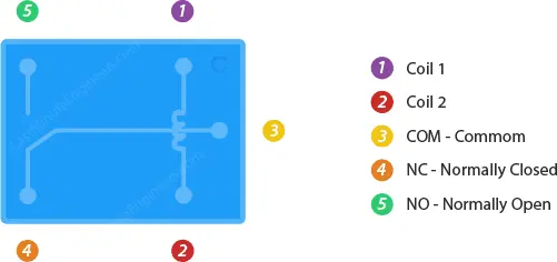
Relays operate based on the principle of electromagnetic induction. When an electric current flows through the coil, it generates a magnetic field around the coil, which attracts or repels a movable contact within the relay arduino. This contact is connected to one or more electrical terminals, allowing it to either make or break an electrical connection.
Relay Operation
There are two main types of relays: normally open (NO) and normally closed (NC). In the default state, a NO relay’s contact is open, meaning no electrical connection exists between its terminals. When the coil is energized, the contact moves and establishes a connection. On the other hand, in the default state of an NC relay, the contact is closed, creating an electrical connection between its terminals. When the coil is energized, the contact moves away, breaking the connection.
Relays are widely used in various applications, especially where low-power control signals need to control high-power devices. They act as switches, allowing the control of devices that operate on different voltage levels or types of current, such as controlling household appliances, motors, lights, or industrial machinery.
Relays play a crucial role in many electronic and electrical systems, providing a safe and efficient means of controlling high-voltage and high-current loads using low-voltage and low-current control signals.
Two Channel Relay Module Hardware Overview
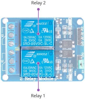
The 2 channel relay module is designed to allow your Arduino to control two high-powered devices. It has two relay arduino, each with a maximum current rating of 10A at 250VAC or 30VDC.
Modules with one, four, and eight channels are also available. You can choose the one that best meets your needs.
Output Terminal Blocks
The output terminal blocks on the 2 Channel Relay Module are the points where the high voltage terminals of each relay are connected. These terminal blocks typically consist of screw terminals that allow easy and secure connections for the devices you want to control.
Each relay has three output terminals: NC (Normally Closed), COM (Common), and NO (Normally Open). These terminals are used to interface the high-voltage devices or loads that you want to switch on or off using the relay.
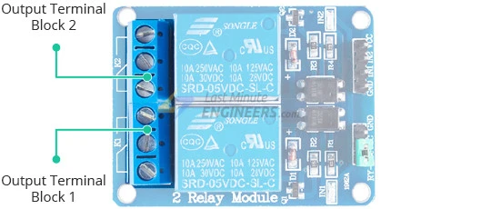
When the relay is in its resting or deactivated state, the connection is established between the COM and NC terminals, creating a normally closed circuit. When the relay is activated or energized, the connection is shifted from COM to NO terminals, creating a normally open circuit.
You can connect your high-voltage devices, such as lamps, fans, solenoids, or other appliances, to these output terminal blocks for control using the relay. Always ensure proper isolation and safety measures when dealing with high-voltage devices to prevent accidents and damage.
Module Control
Module control refers to the process of controlling the operation of the relay module to switch the high-voltage devices connected to it. In the context of the 2 Channel Relay Module, the module control involves activating or deactivating the relays to turn on or off the high-voltage devices.
The Two Channel Relay Module can be controlled through the input pins (IN1 and IN2) of the relay module. These input pins are driven by a microcontroller, such as an Arduino, or any other logic device capable of providing a digital signal.
The module operates on a 5V logic level, and when a logic LOW signal (0V) is applied to the input pins, the relay is activated, and the high-voltage devices connected to the output terminal blocks are turned on. Conversely, when a logic HIGH signal (5V) is applied to the input pins, the relay is deactivated, and the high-voltage devices are turned off.
The control of the relay module can be programmed using suitable code on the microcontroller, and it can be used in various applications, such as home automation, robotics, and industrial control, to switch and control different electrical appliances and devices remotely and automatically. Proper safety measures and isolation should be ensured when dealing with high-voltage devices to prevent potential hazards.
Built-in Optocouplers
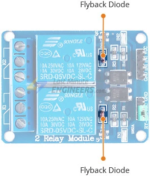
The 2 Channel Relay Module is equipped with built-in optocouplers, which are electronic components that provide electrical isolation between the input control signal and the relay circuit. Optocouplers are used to protect the controlling device (such as an Arduino or microcontroller) from potential electrical faults or voltage spikes that may occur in the relay circuit or high-voltage devices being controlled.
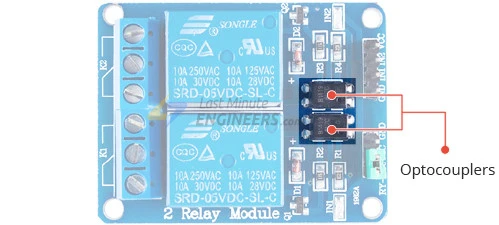
The optocouplers work by using an infrared LED and a phototransistor sealed in a light-tight housing. When a control signal is applied to the input pins of the 2 relay module, the infrared LED is activated, emitting light. This light is detected by the phototransistor, which in turn conducts current in the output circuit of the optocoupler. This creates a galvanic isolation between the input and output sides, allowing the control signal to be safely transmitted without direct electrical connection.
By incorporating optocouplers in the relay module, any potential high-voltage disturbances or voltage transients that occur in the relay circuit will be isolated from the control circuit, preventing damage to the controlling device. This additional layer of protection makes the relay module more reliable and safer to use in various applications, especially when dealing with high-voltage loads or critical electronic components.
Power Supply Selection Jumper
The 2 Channel Relay Module includes a power supply selection jumper that allows you to choose how the relay module is powered.
When the jumper is in place, it connects the header pins labeled JD-VCC and VCC. In this configuration, the relay module is powered directly from the same power supply as the controlling device (such as an Arduino or microcontroller). This means that the relay’s electromagnet is energized using the same 5V power supply that powers the controlling device. In this case, the relay module and the controlling device are not physically isolated from each other.
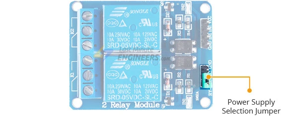
On the other hand, if you remove the jumper, the relay module becomes physically isolated from the controlling device. This means that you need to provide a separate 5V power supply voltage to the JD-VCC and GND pins on the relay module. In this configuration, the controlling device and the relay module operate independently with their own power sources.
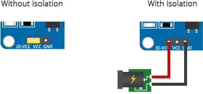
The power supply selection jumper provides flexibility in how you power the relay module based on your specific application requirements. If you prefer a simpler setup and want to power both the controlling device and the relay module with the same power supply, you can keep the jumper in place. However, if you need electrical isolation between the controlling device and the relay module or if you want to use different power sources for each, you can remove the jumper and supply power separately to the 2 relay module.
Module Power
The 2 Channel Relay Module operates on a 5-volt power supply. It requires a 5V DC power source to power its internal circuitry and control the relays. The relay module can draw approximately 140mA of current when both relays are activated, which means it consumes around 70mA for each relay.
It’s important to note that if the built-in optocouplers on the relay module are enabled, you will need to provide two separate 5V power sources. One power source will be used to power the controlling device (such as an Arduino or microcontroller), and the other will be used to power the relay module through the JD-VCC and GND pins. This configuration ensures complete electrical isolation between the controlling device and the relay module, providing an extra layer of protection in case of major failures on the relay’s AC load, such as lightning strikes or voltage spikes.
However, if you choose not to use the optocouplers and keep the power supply selection jumper in place, the relay module can be powered directly from the same 5V power supply that powers the controlling device. In this case, the relay module and the controlling device are not physically isolated from each other, but it simplifies the setup as it requires only one power supply.
2 Channel Relay Module Pinout
Let’s take a look at the pinout.
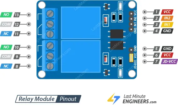
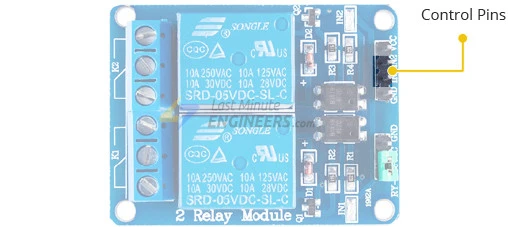
Control Pins:
The control pins on the 2 channel relay module are IN1 and IN2. These pins are used to control the relay. They are active low, which means that pulling them LOW activates the relay, and pulling them HIGH deactivates it. By controlling the state of these pins, you can turn the relay ON or OFF, thereby controlling the connected device or load.
Power Supply Selection Pins:
The power supply selection pins on the 2 channel relay module are JD-VCC and VCC.
JD-VCC provides power to the relay’s electromagnet. When the jumper is in place, JD-VCC is shorted to VCC, allowing the electromagnets to be powered by the Arduino’s 5V line. In this case, both the relay module and the Arduino share the same power supply.
If you remove the jumper cap, JD-VCC and VCC are disconnected. In this configuration, you need to provide a separate 5V power supply to the JD-VCC pin to power the relay’s electromagnets independently from the Arduino’s power supply. This physical isolation of power can be useful in certain situations to protect the Arduino and the relay module from potential electrical interference or issues in the connected devices.
Output Terminals:
The output terminals on the 2 channel relay module are COM (Common), NC (Normally Closed), and NO (Normally Open).
- COM (Common): This terminal is connected to the device or load that you want to control. When the relay is not activated (in its default state), the COM terminal is electrically connected to the NC (Normally Closed) terminal.
- NC (Normally Closed): In the default state of the relay (when it is not activated), the NC terminal is electrically connected to the COM terminal, allowing the current to flow through the normally closed circuit. When the relay is activated, the NC circuit is interrupted or “opened,” breaking the connection.
- NO (Normally Open): In the default state of the relay, the NO terminal is not connected to the COM terminal. When the relay is activated, the NO circuit is completed or “closed,” allowing the current to flow through the normally open circuit.
These three terminals allow you to choose whether the controlled device is normally on or off when the relay is not activated, and you can use the relay to switch between these states by activating or deactivating it.
Wiring a 2 Channel Relay Module to an Arduino
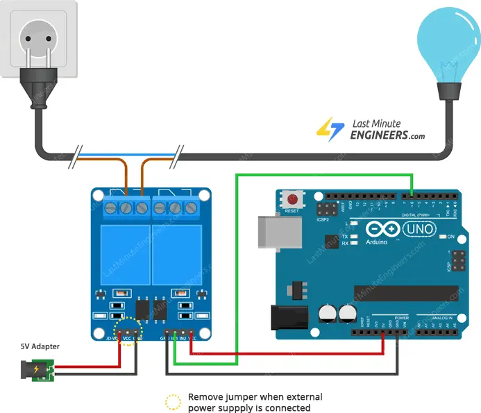
To wire a two channel relay module to an Arduino, follow these steps:
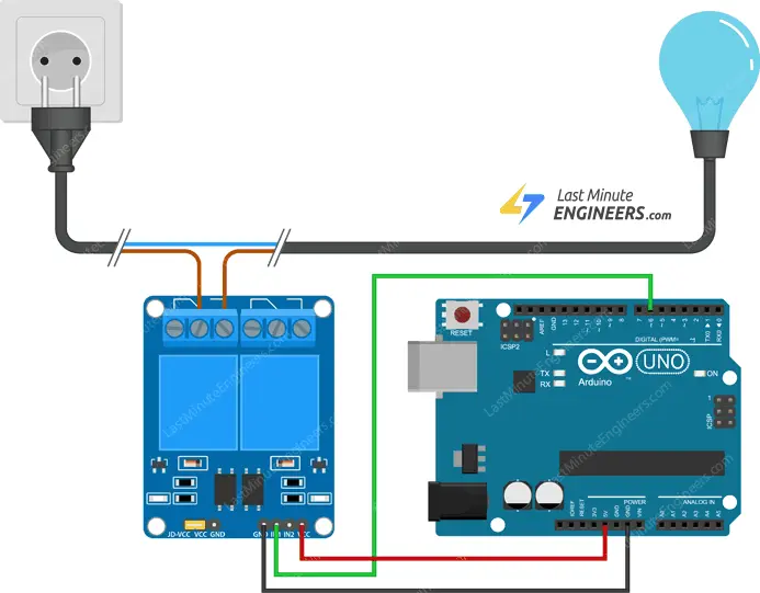
- Connect the VCC pin of the relay module to the Arduino’s 5V pin and the GND pin to the ground (GND) pin on the Arduino.
- Connect digital pin 6 of the Arduino to the IN1 input pin on the relay module. This will be used to control one of the relays.
- If you want to use the second relay, connect another digital pin (e.g., pin 5) of the Arduino to the IN2 input pin on the relay module.
- Connect the relay module to the AC-powered device you want to control, such as a lamp. To do this, cut the live AC line and connect one end of the cut wire (coming from the wall) to the COM (common) pin on the relay module.
- Connect the other end of the cut wire to either the NO (normally open) or NC (normally closed) pin on the relay module, depending on your desired initial state for the device.
- If you want to keep the Arduino and the 2 relay module isolated, remove the jumper between the VCC and JD-VCC pins on the relay module. Then, provide a separate 5V power supply voltage to the JD-VCC and GND pins on the relay module, and connect the GND of this power supply to the Arduino’s GND pin.
Ensure you take the necessary precautions and follow safety guidelines when working with high-voltage AC devices. Double-check your connections before powering the circuit and test the functionality of the relay module with your connected device.
Parts Required
| Component Name | Buy Now |
| Arduino Uno REV3 | Amazon |
| 2 Channel DC 5V Relay Module | Amazon |
| Breadboard | Amazon |
| BOJACK 1000 Pcs 25 Values Resistor Kit 1 Ohm-1M Ohm with 5% 1/4W | Amazon |
Arduino Example Code
Controlling a relay module with the Arduino is as easy as controlling an LED. Here’s a simple code that will activate the relay arduino for 3 seconds and then deactivate it for 3 seconds.
int RelayPin = 6;

void setup() {
	// Set RelayPin as an output pin
	pinMode(RelayPin, OUTPUT);
}

void loop() {
	// Let's turn on the relay...
	digitalWrite(RelayPin, LOW);
	delay(3000);

	// Let's turn off the relay...
	digitalWrite(RelayPin, HIGH);
	delay(3000);
}
Code Explanation:
The sketch begins by declaring the pin to which the relay module’s input pin is connected.
int RelayPin = 6;
In the setup function, we configure the input pin to behave as an output.
pinMode(RelayPin, OUTPUT);
In the loop function, we turn the device ON/OFF by pulling the relay pin LOW/HIGH.
digitalWrite(RelayPin, LOW) pulls the pin LOW, whereas digitalWrite(RelayPin, HIGH) pulls the pin HIGH.
digitalWrite(RelayPin, LOW);
delay(3000);

digitalWrite(RelayPin, HIGH);
delay(3000);
Related article
- Interfacing a 4×4 Keypad with Arduino UNO: Step-by-Step Guide
- How to Interface a Micro SD Card with Arduino
- Arduino and MCP2515: Build Your Own CAN Bus Network
- Interface a 2-Axis Joystick with Arduino: A Processing Tutorial
- DS3231 RTC Module: Seamless Integration with Arduino
- Step-by-Step Guide: Interface DS1307 RTC Module with Arduino


