
When selecting a motor for your project, it is crucial to choose the appropriate one for the task at hand. If precise positioning is required, a servo motor is typically the ideal choice. By providing instructions on where to position, servo motors will accurately execute the desired movements. It’s as straightforward as that!
Servo motors find utility in a wide range of robotics projects, including steering the front wheels of an RC model or rotating a sensor on a robotic vehicle.
What is a Servo and what makes it precise?
A servo is a type of motor specifically designed for precise control over physical movement. Unlike continuous rotation motors, servos are capable of moving to a specific position. They are convenient to use as they have a built-in motor driver, simplifying the connection and control process.
Servos consist of a small DC motor connected to an output shaft through gears. The output shaft drives a servo horn and is also connected to a potentiometer (pot).
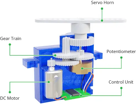
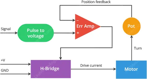
The potentiometer acts as a position feedback device, providing information about the motor’s current position to the error amplifier in the control unit. The control unit compares this feedback to the target position.
Based on the difference between the current and desired positions (the error), the control unit adjusts the motor’s position to align with the desired position.
In control engineering, this mechanism is referred to as a servomechanism, or simply a servo. It operates as a closed-loop control system, utilizing negative feedback to regulate the motor’s speed and direction, ultimately achieving the desired outcome with precision.
How Do Servo Motors Work?
Servo motors are controlled by sending a series of pulses to them. Typically, a servo motor expects a pulse every 20 milliseconds, which translates to a signal frequency of 50Hz.
The duration or length of the pulse determines the position of the servo motor.
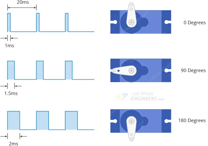
- A short pulse with a duration of 1 ms or less will rotate the servo to 0 degrees, which is one extreme position.
- A pulse duration of 1.5 ms will rotate the servo to 90 degrees, which corresponds to the middle position.
- A pulse duration of around 2 ms will rotate the servo to 180 degrees, which represents the other extreme position.
Pulses within the range of 1 ms to 2 ms will result in the servo motor moving to a position that is proportional to the pulse width. The animation below illustrates the relationship between the pulses and the corresponding positions of the servo motor.

Servo Motor Pinout
Servo motors usually have three pins, as shown in the pinout below:
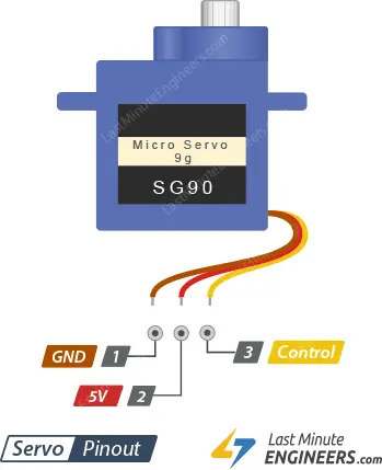
GND: This pin is connected to the ground or negative terminal.
5V: This pin is connected to the positive voltage supply, usually 5 volts.
Control: This pin is used to send control signals to the servo motor to determine its position and movement.
While the wire colors may vary depending on the servo motor, it is common to find the red wire connected to the 5V pin, the black or brown wire connected to the GND pin, and the control wire in colors such as orange or yellow.
Wiring Servo Motor to Arduino UNO
To connect the servo motor to the Arduino, follow these steps:
We will be using an SG90 Micro Servo Motor for our experiments. This servo motor operates on a voltage range of 4.8-6VDC, with 5V being the typical voltage. It has a rotation capability of 180 degrees, with 90 degrees in each direction.
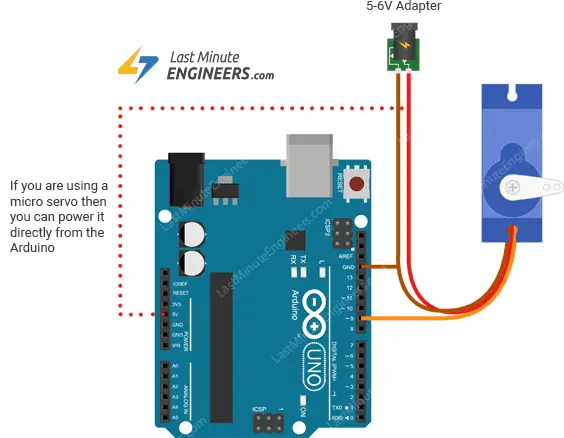
The servo motor has low power requirements, drawing approximately 10mA when idle and 100mA to 250mA when in motion. This means we can power it directly from the Arduino’s 5-volt output.
If your servo motor requires more than 250mA, it is recommended to use a separate power supply to meet its power demands.
Connect the red wire from the servo motor to the Arduino’s 5V pin, providing it with power. Connect the black or brown wire to the ground (GND) pin on the Arduino to establish a common ground.
Finally, connect the orange or yellow wire from the servo motor to a PWM-enabled pin on the Arduino. In this example, we will use pin #9 for controlling the servo motor.
Refer to the table below for a summary of the pin connections:
| Servo Motor Pin | Arduino Pin |
|---|---|
| Red (Power) | 5V |
| Black/Brown (GND) | GND |
| Orange/Yellow (Control) | PWM-enabled pin (e.g., pin #9) |
The image below provides a visual representation of how to connect an SG90 servo motor to the Arduino.
Parts Required
| Component Name | Buy Now |
| Arduino Uno REV3 | Amazon |
| SG90 9G Micro Servo Metal Geared Motor Kit for RC Robot | Amazon |
| Taiss 40PCS Potentiometer Kit with Rotary knobs | Amazon |
| Breadboard | Amazon |
| BOJACK 1000 Pcs 25 Values Resistor Kit 1 Ohm-1M Ohm with 5% 1/4W | Amazon |
Arduino Example 1 – Sweep
To begin, let’s use one of the built-in examples provided by the Arduino IDE. Follow these steps:
- Open the Arduino IDE and navigate to the Examples sub-menu.
- Select the “Servo” category and open the “Sweep” sketch.
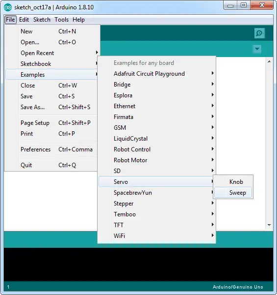
- Upload the sketch to your Arduino board. Once uploaded, the shaft of your servo motor will start sweeping back and forth across a 180-degree range.
Below is the code for the Sweep sketch:
#include <Servo.h>

int servoPin = 9;
Servo servo;
int angle = 0;  // servo position in degrees

void setup() {
    servo.attach(servoPin);
}

void loop() {

    // scan from 0 to 180 degrees
    for(angle = 0; angle < 180; angle++) {
        servo.write(angle);
        delay(15);
    }

    // now scan back from 180 to 0 degrees
    for(angle = 180; angle > 0; angle--) {
        servo.write(angle);
        delay(15);
    }
}
Code Explanation:
The code uses the Servo library, which is included at the beginning. The servo motor is connected to pin 9 of the Arduino (servoPin).
In the setup() function, we attach the servo to the designated pin.
The loop() function contains two for loops that control the servo’s movement. The first loop moves the servo from 0 to 180 degrees, incrementing the angle in each iteration. After reaching 180 degrees, the second loop moves the servo back from 180 to 0 degrees, decrementing the angle.
During each iteration, the servo.write(angle) command sets the servo’s position to the current angle. A small delay of 15 milliseconds is added between each angle change to provide a smooth sweep motion.
Once you upload the sketch, you will observe the servo motor sweeping back and forth continuously.
Troubleshooting
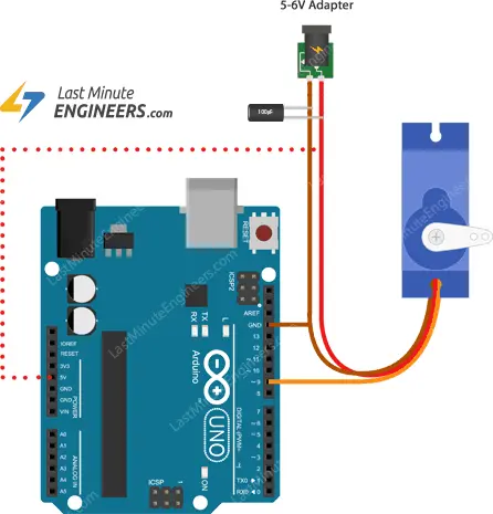
Occasionally, you may encounter issues with your servo, especially if you are powering it directly from the Arduino. This can occur because the servo requires a significant amount of power, particularly during startup, which can lead to the Arduino board resetting.
To resolve this problem, you can add a large electrolytic decoupling capacitor (470µF – 1000µF) across the power input. Ensure that the longer lead of the capacitor is connected to the 5V pin and the negative lead is connected to GND.
The capacitor acts as an electrical reservoir, providing additional power to the servo during startup. By drawing power from both the Arduino supply and the capacitor, a steady current flow is maintained, resulting in smoother operation.
Arduino Example 2 – Controlling Servo with a Potentiometer
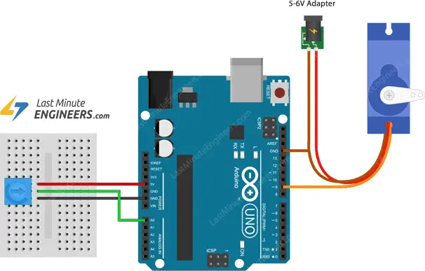
In this example, we will incorporate a potentiometer to manually adjust the servo’s position. This project is particularly useful for controlling the pan and tilt of a sensor connected to a servo.
Wiring
We will reuse the wiring from the previous example but add a 10KΩ potentiometer. Connect one end of the potentiometer to ground, the other end to 5V, and the wiper (middle pin) to analog input A0.
Arduino Code
The code for making the servo follow the position of the knob is simpler compared to the sweeping example.
#include <Servo.h>

int potPin = 0;
int servoPin = 9;
Servo servo;

void setup() {
    servo.attach(servoPin);
}

void loop() {
    int reading = analogRead(potPin);
    int angle = map(reading, 0, 1023, 0, 180);
    servo.write(angle);
}
Code Explanation
In this code explanation, we will focus on the Arduino sketch that controls the servo motor using a potentiometer.
A new variable named potPin is introduced to represent the analog pin A0, which is connected to the potentiometer.
int potPin = 0;
Inside the loop() function, the value from the potentiometer is read using the analogRead() function and stored in the variable reading.
int reading = analogRead(potPin);
To map the range of the potentiometer reading (0-1023) to the range of servo motor movement (0-180 degrees), the map() function is used. The angle variable is assigned the mapped value.
int angle = map(reading, 0, 1023, 0, 180);
Finally, the write() function is used to set the position of the servo motor to the angle determined by the potentiometer.
servo.write(angle);
By continuously reading the potentiometer value and updating the servo motor position accordingly, the servo will track the position of the potentiometer knob as it is adjusted.
Related article
- Interfacing 28BYJ-48 Stepper Motor Arduino using ULN2003 Driver
- Interfacing DC Motors with Arduino using L298N Motor Driver Module
- Stepper Motor Control with Arduino: L298N Motor Driver Interface
- Step-by-Step Guide: Arduino Stepper Motor Control with A4988 Driver
- Step-by-Step Guide: Arduino Stepper Motor Control with DRV8825 Driver
- Arduino Motor Control: DRV8833 Motor Driver for DC Motors
- Arduino Motor Control: L293D Motor Driver for DC Motors
- Step-by-Step Guide: L293D Stepper Motor Driver with Arduino


