
The bootloader serves as the initial code that activates whenever a microcontroller is powered on or undergoes a reset. It functions akin to the BIOS found in personal computers, which initializes upon powering up the system. In the case of BIOS, it awaits user input to modify boot options or settings. Absent such input, it proceeds with the pre-installed operating system.
Similarly, the Arduino bootloader operates upon power-up or reset, seeking external inputs for uploading new programs. Without such inputs, it proceeds to execute the previously uploaded program.
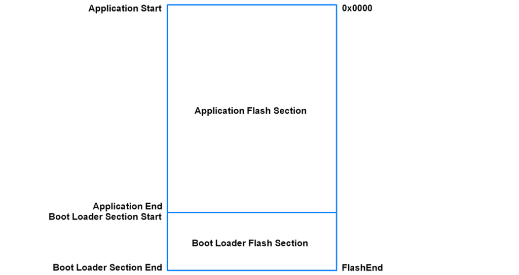
Arduino utilizes AVR microcontrollers for its platforms, which include program memory sections, as illustrated above. The bootloader section resides at the base of the flash memory.
The bootloader program is housed within the bootloader section, while the application program resides within the application section.
Parts Required
| Component Name | Buy Now |
| Arduino Uno REV3 | Amazon |
How Bootloader Starts
Upon reset or power-up, a microcontroller typically commences program execution from the reset vector, located at memory address 0x0000.
However, if a bootloader is installed on the microcontroller, we have the option to adjust this reset vector address (0x0000) to point to the beginning of the bootloader section. Consequently, each time the microcontroller is reset or powered up, it initiates program execution from the bootloader section.
This behavior is mirrored in Arduino bootloaders, where the microcontroller, when reset or powered up, executes the bootloader program, starting from the initial address of the bootloader section.
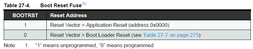
Consulting the datasheet of AVR microcontrollers, which are utilized in Arduino, reveals that the Boot Reset Fuse can be programmed to direct the Reset Vector to the Boot Flash start address after a reset, as illustrated in the figure below.
Therefore, we have the capability to configure the reset vector to align with the start of the bootloader section upon power-up or reset.
The Purpose of a Bootloader
In the realm of microcontrollers, bootloaders are frequently utilized to streamline the process of uploading programs onto the microcontrollers. They can also serve to initialize IO devices connected to the microcontrollers before the main application program commences.
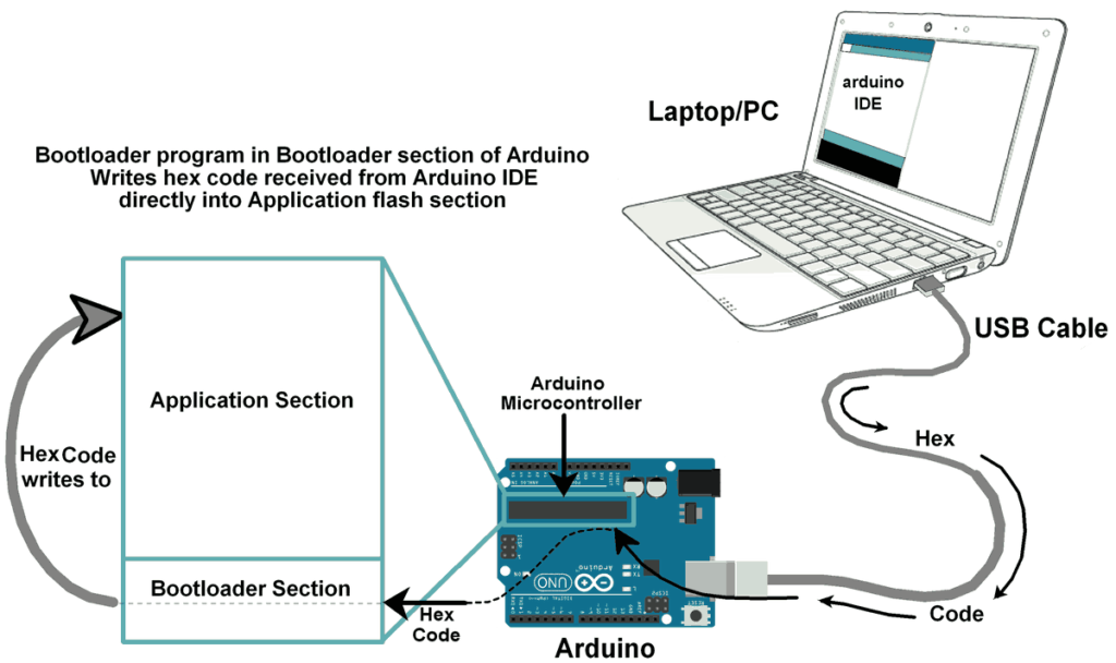
Arduino bootloaders employ straightforward serial communication (UART) to download the program’s hex file and write it into the application section.
Exploring the Bootloader
Let’s delve into the intricacies of how the Arduino Bootloader is constructed and how it interacts with the Arduino IDE during program uploads.
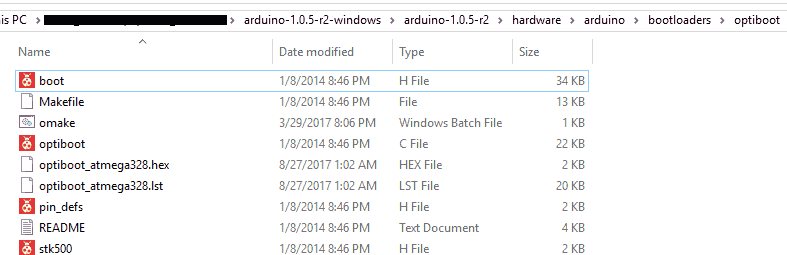
The Arduino bootloader program can be located at:
as depicted below.
The boot header file (boot.h) is imported from the AVR toolchain. This is a modified or optimized version of the AVR toolchain boot header file (<avr/boot.h>). You can find the AVR boot header file at:
The AVR boot header file employs the “sts” instruction (requiring two machine cycles) to access the SPM register, whereas the boot header file used in the Arduino bootloader utilizes the “out” instruction (requiring only one machine cycle) to access the SPM register. This crucial optimization is already integrated into the AVR toolchain boot header file for smaller devices.
The boot header file encompasses functions related to writing/reading flash memory (in a page-by-page manner) and functions for writing/reading fuse, lock, and signature bits.
The stk500 header file (stk500.h) contains the STK500 commands utilized for reliable handshaking communication between Arduino and the avrdude program during hex file uploads.
The pin definition header file (pin_defs.h) contains port definitions for the LED (Arduino’s onboard LED), which indicates status by blinking while flashing the Arduino.
The optiboot.c file encompasses the main program flow of the bootloader (i.e., receiving hex data serially and writing it to program memory). Other files (boot.h, pin_defs.h, stk500.h) are included in the optiboot.c file.
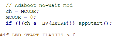
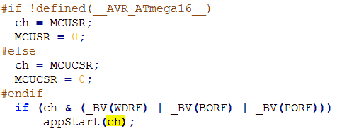
The Optiboot program commences with the MCU Status Register (MCUSR), which provides information about the reset source that caused the reset. If the reset source is not external (caused by pulling the reset pin low), the bootloader will directly initiate the application program. As illustrated below, it will call the appStart() function, which then jumps to the reset address (0x0000).
If the reset source is external (caused by pulling the reset pin low), the bootloader avoids jumping directly to the application code and instead prepares for serial communication with avrdude running on a PC/laptop to read the hex file and flash it into the program memory.
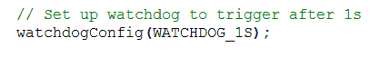
A watchdog timer is set for a 1-second timeout in the program, ensuring a reset if there’s any error during code upload or to reset after program memory write completion.
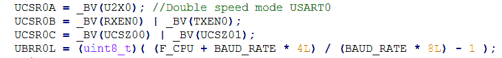
The bootloader then initializes serial communication (UART) to communicate with the Arduino IDE running on a PC/laptop.
Following these initializations, it enters a perpetual loop to read bytes (command/data byte) serially using the protocol employed by STK500.
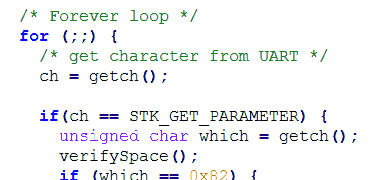
The program memory is written/updated in a page-by-page fashion. The page size varies depending on the controller. For instance, the Atmega328/328P has a page size of 64 words (i.e., 128 bytes), whereas the Atmega88A/88PA has a page size of 32 words (i.e., 64 bytes).
The process of writing to program memory is conducted page by page:
- Within the perpetual loop mentioned earlier, hex bytes received serially from the Arduino uploader running on a PC/laptop are first copied to temporary data memory (RAM).
- After copying page-sized hex bytes into temporary data memory, the process of erasing the first page of program memory is initiated.
- Once the page is erased, it is filled (not written) with hex bytes stored in temporary data memory.
- Using the SPM page write instruction, the page is successfully written/updated.
- This process of reading data from serial and writing it to program memory in a page-by-page fashion continues until all hex bytes are written/updated in the program memory.
- Upon completion of the hex file write operation, the reverse process is initiated: reading from program memory and sending it serially to the PC/laptop to verify whether the hex file has been written/updated in the program memory.
Below is a sample page write function provided in the boot header file:
#include <inttypes.h>
#include <avr/interrupt.h>
#include <avr/pgmspace.h>
void boot_program_page (uint32_t page, uint8_t *buf)
{
	uint16_t i;
	uint8_t sreg;
	// Disable interrupts.
	sreg = SREG;
	cli();
	eeprom_busy_wait ();
	boot_page_erase (page);  //erase page
	boot_spm_busy_wait ();      // Wait until the memory is erased.

	for (i=0; i<SPM_PAGESIZE; i+=2)
	{
		// Set up word from temp buffer.
		uint16_t w = *buf++;
		w += (*buf++) << 8;
		boot_page_fill (page + i, w);  //fill (page + i ) address with word
	}
	boot_page_write (page);     // Store/write buffer in flash page.
	boot_spm_busy_wait();       // Wait until the memory is written.
	// Reenable RWW-section again. We need this if we want to jump back
	// to the application after bootloading.
	boot_rww_enable ();
	// Re-enable interrupts (if they were ever enabled).
	SREG = sreg;
}
All of the above provides a basic understanding of how a hex file is written into program memory. The functions used in the above program, such as boot_page_fill (page address, word data), boot_page_write (page address), boot_spm_busy_wait(), etc., are available in the boot header (boot.h) file and are written with inline assembly instructions.
How does a program residing at the bottom of the program memory itself manage to write into the program memory? i.e., how does the program in the boot section write into the application section? This is made possible by AVR microcontrollers, which provide a self-programming mechanism (SPM) for downloading and uploading code by the microcontroller itself. The Self-Programming can utilize any available data interface and associated protocol to read code and write (program) that code into the Program memory.
Programming Arduino with its IDE
The Arduino bootloader employs the serial protocol (UART) to retrieve the program hex file from a PC/laptop. On the PC/laptop end, the Arduino IDE is active, which compiles the application program and transmits its compiled hex code to the Arduino board via a USB cable, serially.
The Arduino IDE utilizes the avrdude tool for uploading and downloading code/data content to/from the ROM/EEPROM of AVR microcontrollers.
AVRDUDE (AVR Downloader Uploader) is a software designed for downloading and uploading data to the on-chip memories of Atmel’s AVR microcontrollers. It can program the Flash and EEPROM, and with support for the serial programming protocol, it can also program fuse and lock bits.
Avrdude employs the STK500 communication protocol to upload the compiled hex file to Arduino serially. Hence, we include and utilize the STK500 commands header file in the bootloader program.
STK500 communication facilitates the exchange of data between avrdude (operating on the PC/laptop side) and the bootloader (operating on the Arduino side) for writing/reading the hex file.
Now, let’s begin by examining how to upload the bootloader program into the boot section.
How to upload Bootloader first
Before utilizing the bootloader, it’s essential to write/install it into the bootloader section of the program memory.
Typically, we program any IC prior to soldering it onto a PCB. Many microcontroller manufacturers (e.g., Atmel, Microchip) offer a specialized In System Programming (ISP) method known as In-Circuit Serial Programming (ICSP). In such methods, an ISP header is provided on the board for flashing it with an external programmer.
Arduino features an onboard ICSP header for programming, as illustrated below.
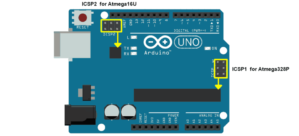
In the case of the Arduino UNO, two ICSP headers are present: one for the ATmega16U2 and another for the ATmega328. To flash the bootloader, we utilize the ICSP header for the ATmega328.
We can construct and flash the Arduino bootloader using Atmel Studio and USBasp (an in-circuit programmer). For guidance on how to build and flash the hex file into AVR microcontrollers, refer to “Getting Started with Atmel Studio.”
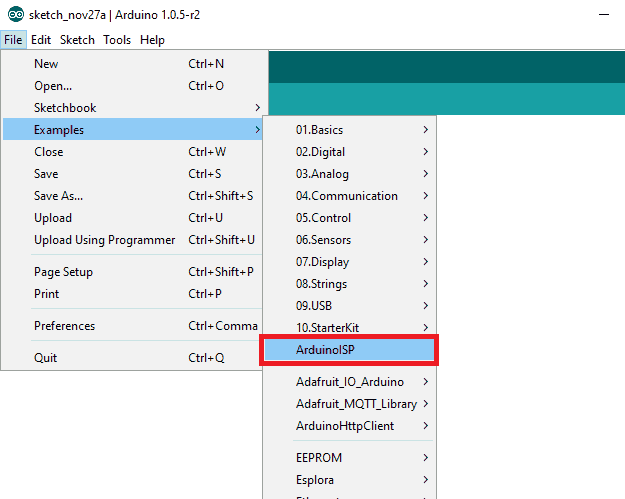
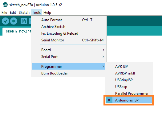
Alternatively, we can flash the bootloader using another Arduino. If we have a second Arduino board available, we can use it as an ISP programmer. Open the Arduino IDE and access the ArduinoISP example from its example menu, as demonstrated below.
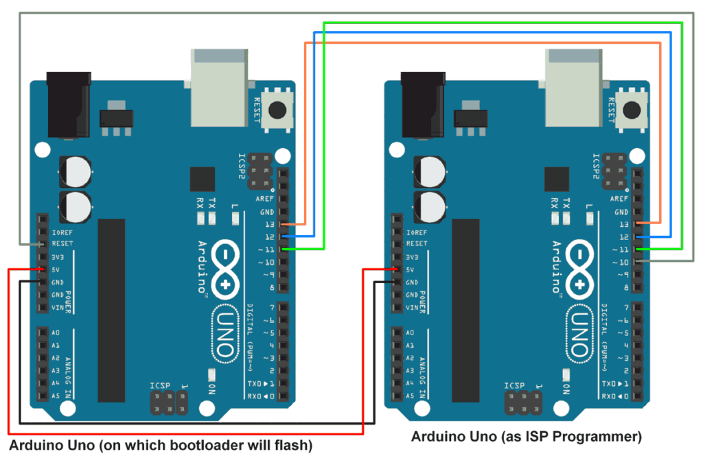
Upload the ArduinoISP program onto the Arduino board designated as the ISP programmer. Then, connect this Arduino ISP programmer to the Arduino board intended for programming, as depicted below.
Select the Arduino board (ISP programmer) and choose “Arduino as ISP” as the programmer from the tools option, as shown below.
Simply click on the “Burn Bootloader” option from the tools menu (as seen in the image above) and await the completion of the bootloader burning process. During this process, the LED will blink, indicating activity.
Upon successful burning of the bootloader, the Arduino board on which the bootloader is installed is ready to be programmed.
Modifying the Arduino Bootloader
An alternative version of the Arduino Bootloader is accessible, featuring several improved functions and a significant alteration. The alteration involves passing the reset cause (MCUSR status register) from the bootloader program to the application program via the r2 register. This transmission occurs through the app_start() function, depicted in the figure below.
We’ve included the Atmel Studio 7 project file for this modified version of the Arduino (ATmega328P) bootloader in the attachment section at the end of this document. You can experiment with it as is or customize it according to your preferences.
Numerous options are available for modifying the provided bootloader program to suit our needs. For instance, while the Arduino bootloader utilizes UART serial communication to read the hex file from a PC/laptop, we can also leverage other available serial communication options like SPI or I2C. By utilizing these communication methods, we can read the hex file from an external source such as a memory card or EEPROM.
Bootloader Section Size
Another critical aspect of the bootloader is the available size in the microcontroller for the bootloader section.
Using Arduino as an example, we can observe that the bootloader size is customizable by the user. For instance, the Arduino UNO, which utilizes the Atmega328P AVR microcontroller, has a bootloader size that can be selected according to the specifications provided in its datasheet.
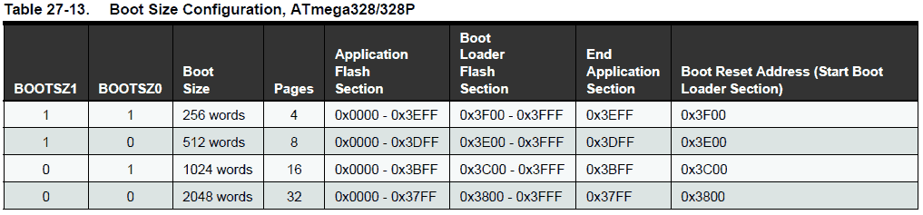
As illustrated in the boot configuration diagram above, we can see that the boot section size is adjustable. The boot size is specified in words, which is half the size in bytes. For example, 256 words equates to 512 bytes.
Additionally, the boot reset start address is set based on the boot size configuration. For instance, if we select a boot section size of 256 words, then the bootloader program must fit within the allocated 256 words (512 bytes) of memory, and its start address will be 0x3F00 (or 0x7E00 in bytes). Consequently, the bootloader program should reside within the memory range of 0x3F00 to 0x3FFF (512 Bytes).
Configuring Atmel Studio Project Properties for Bootloader Development
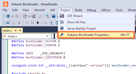
When setting up a new project for Arduino bootloader development in Atmel Studio, it’s essential to make some key adjustments to optimize the project properties. Begin by opening the project property window from the Project menu, as illustrated below.
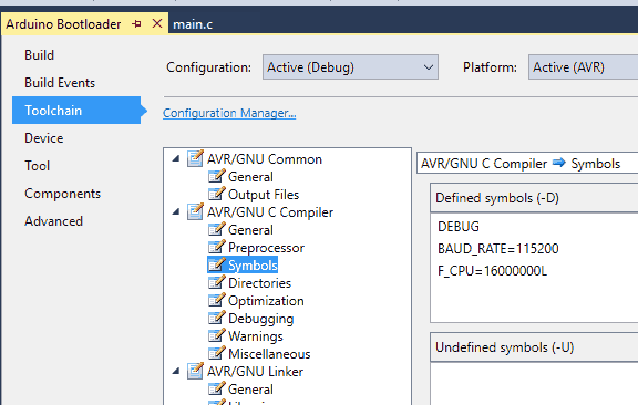
Once the project properties window appears, navigate to Toolchain -> Symbols in AVR/GNU Compiler to define any necessary symbols. In this section, we define the baud rate as 115200 and the frequency as 16000000 Hz, as depicted below.
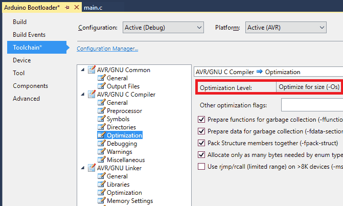
Next, move to the optimization option, just below the Symbols option, and select the optimization level to “Optimize for size (-Os),” ensuring that our code is optimized for minimal size.
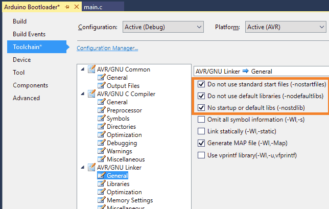
Proceed to the general option in AVR/GNU Linker and enable the first three labels by ticking them since they are not used in the bootloader. These options are:
- Do not use standard start files (-nostartfiles)
- Do not use default libraries (-nodefaultlibs)
- No startup or default libs (-nostdlib)
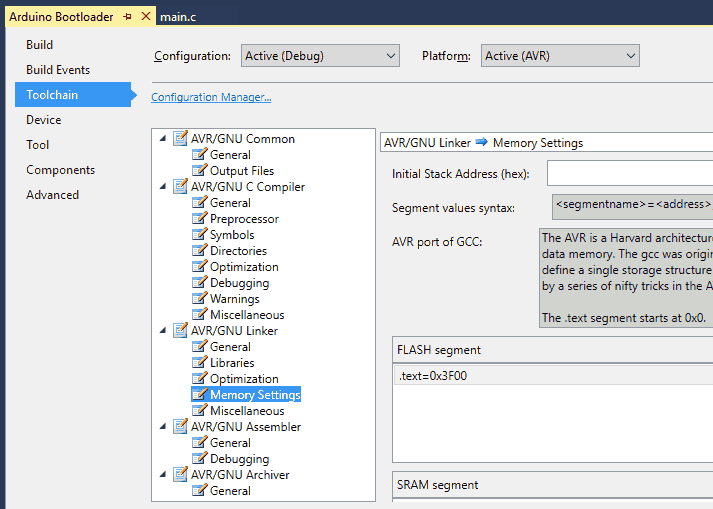
An essential aspect is the memory settings (located in AVR/GNU Linker options), where we define the start address of flash memory segments, SRAM segments, EEPROM segments, and the initial stack address.
For the Arduino bootloader, we select a boot configuration size of 256 words (512 bytes). After every reset or power failure, the controller must first jump to the bootloader section. Therefore, we define the flash segment start address to be the bootloader start address, setting the flash segment with .text=0x3F00 address, as shown below.
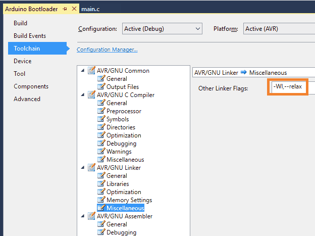
Additionally, we add linker flags used in the relaxation of branches. Nearby functions (within a range of +2k to -2k from the current program memory address) will be called using the RCALL instruction instead of the direct CALL instruction, saving additional cycles required in the call routine.
Related article
- Beginner’s Guide to Arduino Board Setup
- Arduino Basics: Getting Started with DIY Electronics
- Essential Guide to Arduino’s Watchdog Timer
- Mastering Analog-to-Digital Conversion (ADC) in Arduino
- Mastering UART Communication Basics
- Mastering the Basics of SPI Protocol Communication
- Exploring I2C: Essential Communication Protocol Basics
- Serial Communication Essentials: Delving into Arduino USART
- Mastering Digital GPIO: Arduino’s Key to Control


